

VERSION HISTORY
LIRA-FEM
- Mass redistribution
- Damping ratio
- Seismic isolators
- Pushover Analysis
- Finite element "Joint"
- New types of perfectly rigid body (PRB)
- Nonlinear behaviour of soil
- New type of force
- Nonlinear custom cross-sections
- Accounting for orthotropy
- Analysis parameters
- Analysis of reactions
- Stresses and forces
- Dynamics
- Nonlinearity
- Finite elements
- Calculation and Performance
Basic modelling
- Implemented a tool for checking the design model to detect errors in geometry and topology, element properties, loads, and boundary conditions at the stage of creating the design model.
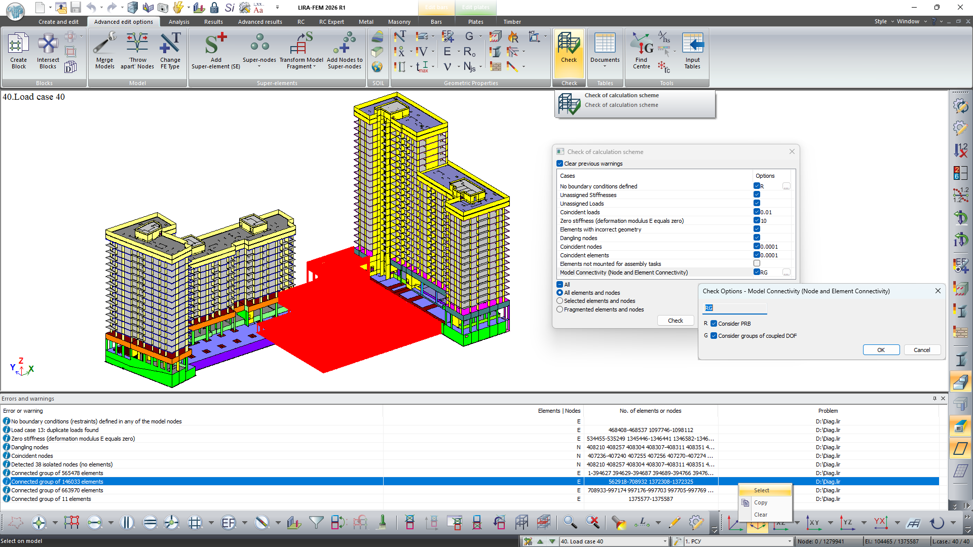
Check of design model
- Expanded functionality for determining the center of gravity (center of mass) and center of stiffness of a flat strictly horizontal fragment of the model (storey). Implemented selection of formulas for calculating moments of inertia of vertical elements. Added consideration of permissible deviation of elements from vertical and the ability to filter adjacent structures. Implemented output of a table with intermediate analysis results for separate groups of vertical elements.
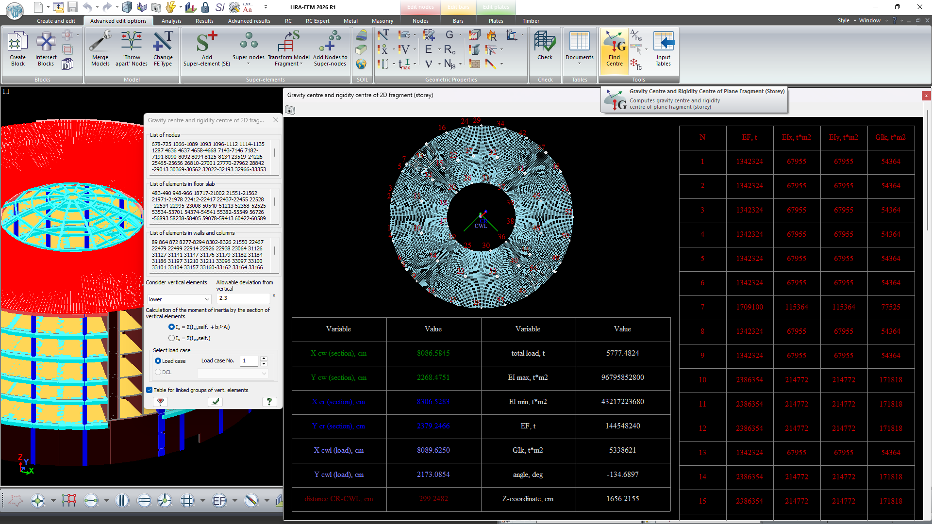
Center of gravity and center of stiffness of a flat fragment (storey)
- Added a command for automatic refinement of selected solid finite elements.
- Expanded functionality for discretizing an existing mesh of plate FEs: added splitting of plates into equal parts along local axes.

Splitting plates into equal parts along local axes
-
Added new filter options (selecting nodes and/or elements on the model that meet specified selection criteria):
- by orientation of finite elements along several directions;
- by target plates of plate analogues;
- by geometry (quality of plate triangulation mesh).
- Added consideration of kinematic links between nodes (perfectly rigid bodies and coupled DOF) when executing the command Select elements adjacent to selected nodes and elements.
- Added new functions simplifying preparation of input data for calculation of load on fragment. Lists can also be formed automatically based on fixed nodes (with restraints applied) and corresponding elements of the model.
- Added a command for synchronizing node and element selection, enabling synchronous select and unselect operations for nodes and elements of the model across all open windows of the current problem.
- Added the ability to save lists of configured scale ranges.
- In the mode of obtaining information about model elements during viewing or editing, the direction of the local coordinate system is now automatically displayed for the selected bar, plate, or solid finite element. This function simplifies control of element orientation.
- In the nonlinear load modeling dialog, an automatic collapse/expand tool for the nonlinear history tree has been added.
- In scale parameters, a Value comparison accuracy setting has been added, allowing refinement of range values for mosaic plots and contour plots of input data of the design model, results of static and dynamic analysis, as well as design results.
- Added the ability to hide selected grid lines and elevations, as well as disable incremental labeling of grid lines.
Note. In version 2026 R1, for unification purposes, FE types for plates have been merged: shell, slab, beam-wall rectangular FEs have been joined to quadrilateral FE types — 11, 15, 21, 23, 41, 45, 221, 223, 241, 245, 281, 341, 441 replaced by 19, 17, 30, 27, 44, 47, 230, 227, 244, 247, 284, 344, 444 respectively. Also, for wall-beams, to unify capabilities (use in models of type 1, 2, 4, 5), quadrilateral FEs 27, 227 have been merged and replaced by 30, 230 respectively, triangular FEs 22, 222 replaced by 24, 224 respectively.