VERSION HISTORY
LIRA-FEM
Cross-Section Design Toolkit
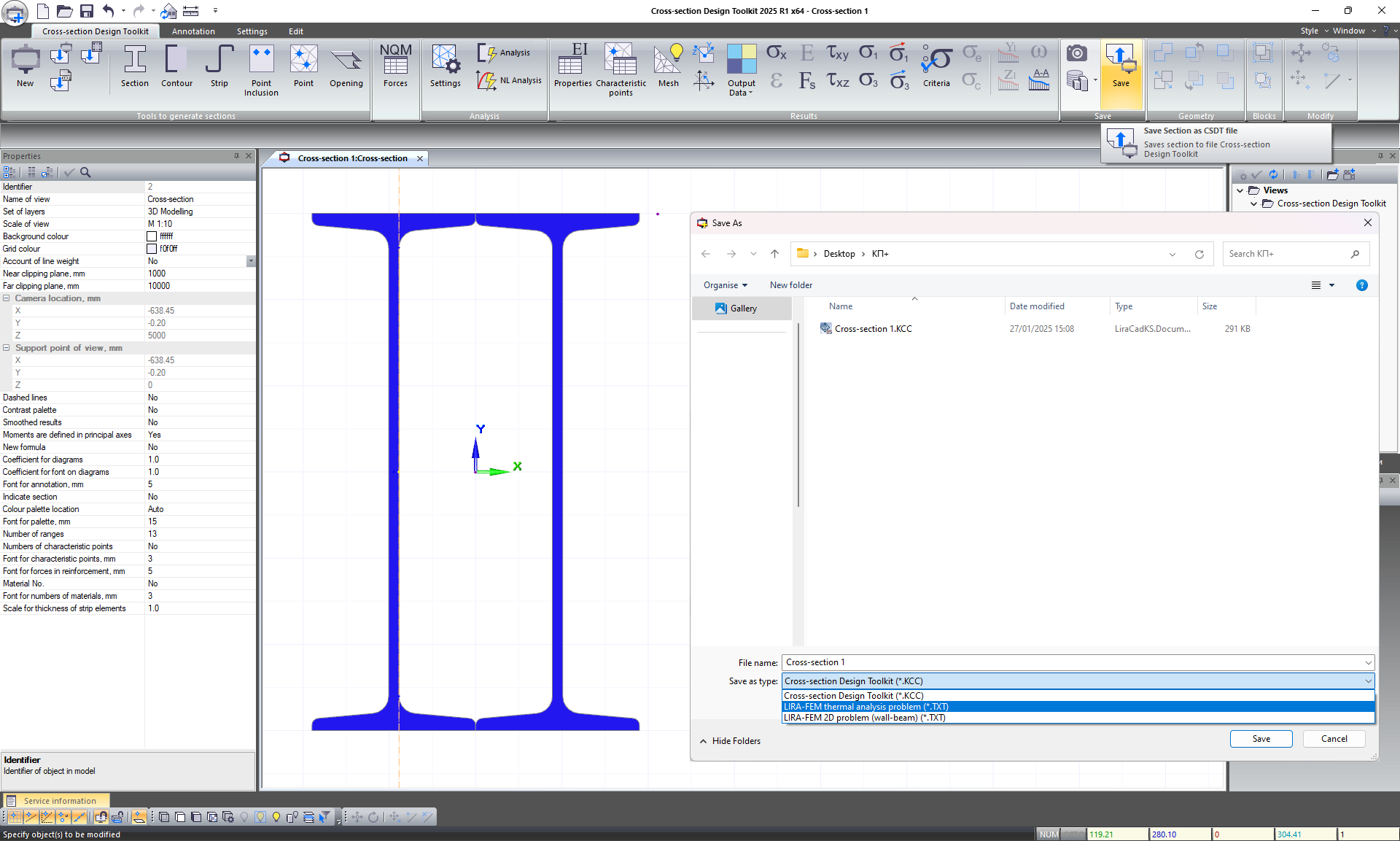
- Added the option to assign linear heat‐technical characteristics to materials, with their subsequent export to the 15th model type.
- Calculation of the sectional moment of resistance of the cross-section has been added to the characteristics table.
Improvements to the "Cross-Section Design Toolkit" module
This module now offers the new option to export files to the 15th model type in the LIRA-FEM software. This feature allows the user to quickly generate design models for the problems with heat transfer analysis. During the export procedure, the proper finite element types and stiffnesses are assigned to all elements; convective heat transfer elements are moved along the outer contour of the section to simulate boundary conditions and external loads.
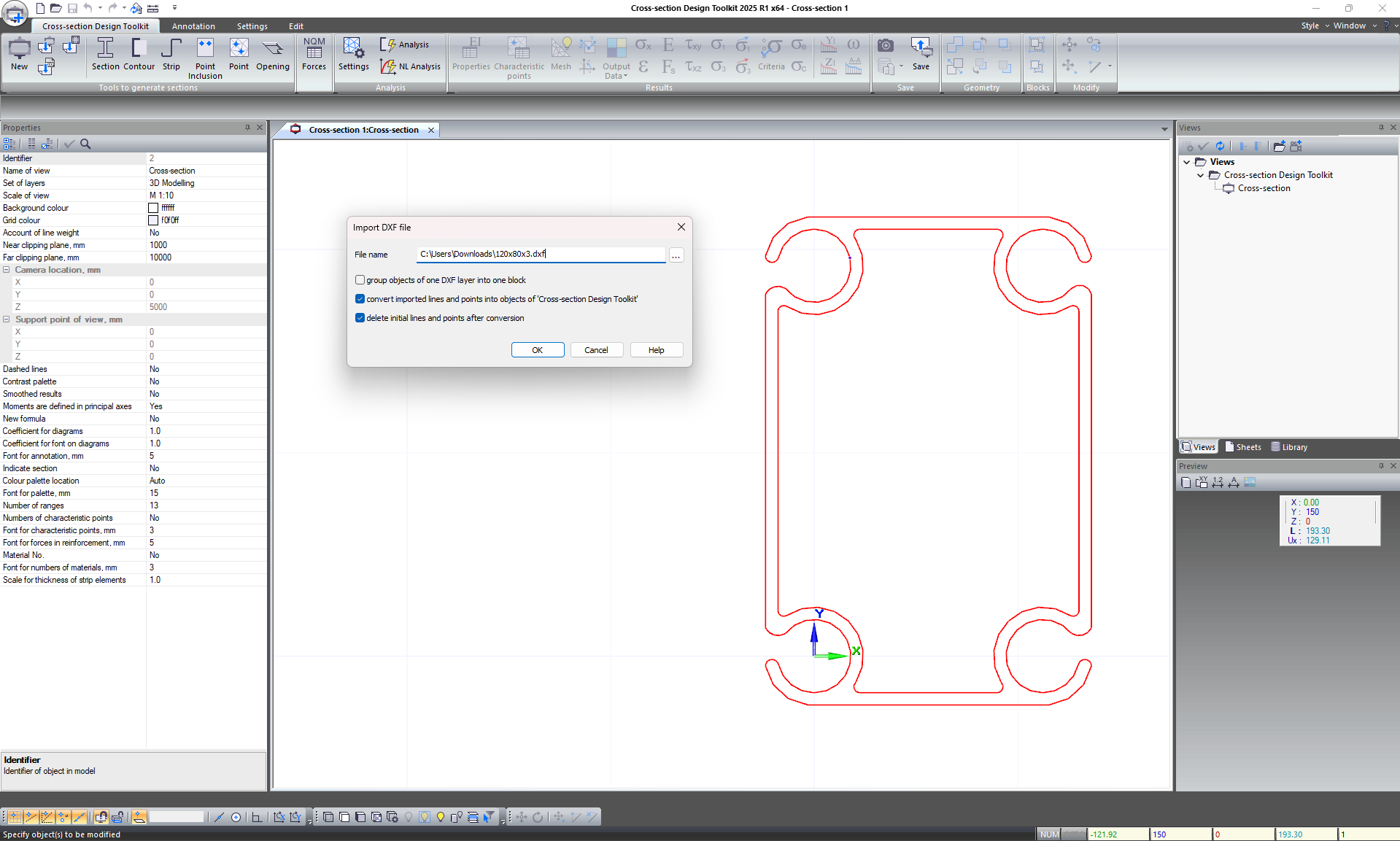
When the geometry is exported from *.dxf file, the arcs and segments that have matching ends in the *.dxf file are now included in the same contour.
Cross-section Design Toolkit
-
Optimised algorithm for calculating geometric properties with cross-sectional dimensions of tens of metres, for example, when calculating the stiffness centres of foundations.
-
Enhanced smoothing function for results obtained on a sparce triangulation mesh.
Improvements to the "Cross-Section Design Toolkit" module
-
New option to export (to VISOR module) the arbitrary cross-section with materials that have nonlinear properties (such as nonlinear stress-strain diagrams for concrete and reinforcement, creep diagrams). Nonlinear arbitrary cross-section may be saved to a separate file and used in VISOR module as a separate type of stiffness. After physically nonlinear analysis of bars with a nonstandard nonlinear cross-section, it is possible to transfer the calculated forces from VISOR module to the "Cross-section Design Toolkit" module.
Important. When such sections are used in FEA, the stiffness in shear and torsion should be calculated for them.
-
New option to import the cross-section based on fire resistance data of elements from VISOR module to "Cross-section Design Toolkit" module, taking into account the change in nonlinear stress-strain diagrams for concrete and reinforcement under exposure of high-temperature according to DSTU-N B EN 1992-1-2:2012.
-
When the table of output data at characteristic points of the cross-section is displayed on the drawing, it is possible to select the drawing sheet on which the table should be placed. It is also possible to select the font size and the option to have a table header.
-
The principal axes calculated in the "Cross-section Design Toolkit" module are now adjusted according to the principal axes in VISOR module and in the FEM solver. Thus, the Y1-axis now always corresponds to an axis with the largest moment of inertia.
-
The sign is inverted for the stresses that are computed from the bimoment.


