

VERSION HISTORY
LIRA-FEM
- Components of BIM technology
- Generating and modifying the model
- Generating and modifying the design model
- Analysis options
- Tools for evaluation of object properties and analysis results
- Analysis & design of reinforced concrete (RC) structures
- RC Expert
- Analysis & design of steel structures
- Soil
- Cross-Section Design Toolkit
- Documentation improvements
Nonlinear volume iterative finite elements
For physically nonlinear iterative solids, the computed parameters of the stress-strain state are visualized as mosaic plots:
- relative strain εmax/εmin in the main material of solids;
- max stress σmax in the main material of solids;
- max stress in the reinforcement along X1, Y1, Z1;
- relative strain in the reinforcement along X1, Y1, Z1.

Loads on fragment
It is possible to define the data and compute loads (nodal reactions) for several groups of nodes and elements simultaneously. The new tool will greatly simplify the evaluation and documentation process. For example, this tool allows the user to obtain reactions for structural elements at the points where they are supported by other elements. In this case, different combinations of elements from which the load is collected are taken into account.

For problems with transient heat transfer analysis, the heat flow at nodes of design model may be calculated. The results can be visualized as mosaic plots and graphs of heat flow variation in time for different groups of nodes and elements.
Nonlinear hinges
The analysis results can be used to generate "force-displacement" and "moment-rotation" graphs for two-node and one-node FEs of nonlinear elastic springs with an account of unloading with initial stiffness (FEs 295, 296). These graphs make it possible to see how nonlinear supports and nonlinear hinges behave based on loading history, which greatly enhances comprehension and evaluation of the structure's behaviour.
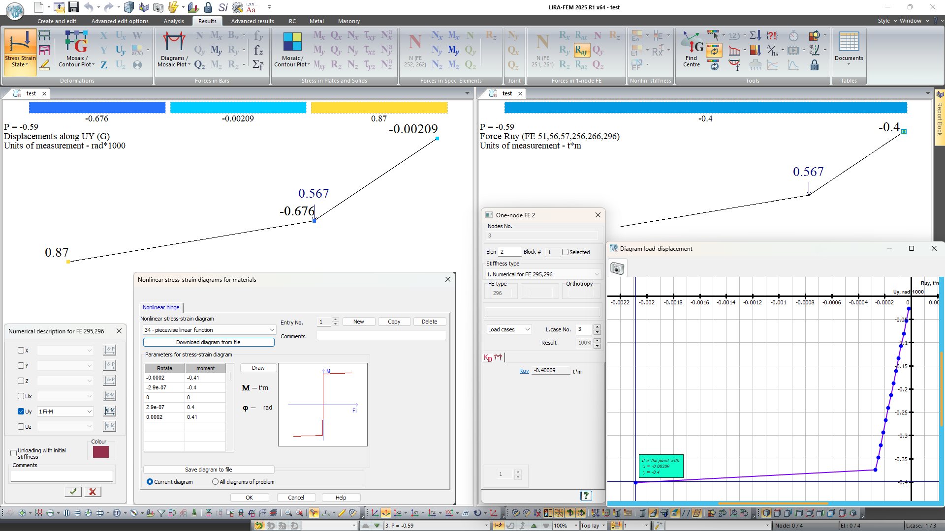
Analysis options – Enhancements
In addition to the existing combinations generated by DCF and DCL, a new algorithm is implemented to determine combinations of individual load cases that may be significant (the most dangerous) for each checked element and each node of the design model. The new method combines all the advantages of the previous methods and adds new features: work with a large number of combinations (more than 1000 combinations), user-defined settings for types and subtypes of load cases, user-defined combination formulas, formula representation of logical relationships, matrix representation of mutually exclusive load cases and much more.

A new type of uniformly distributed load on bars and plates is implemented in problems with time history analysis. The following load variation diagrams are available: piecewise linear load with arbitrary or uniform step, as well as sinusoidal load.

New option to define multiple time history analyses with different parameters within a single design model.
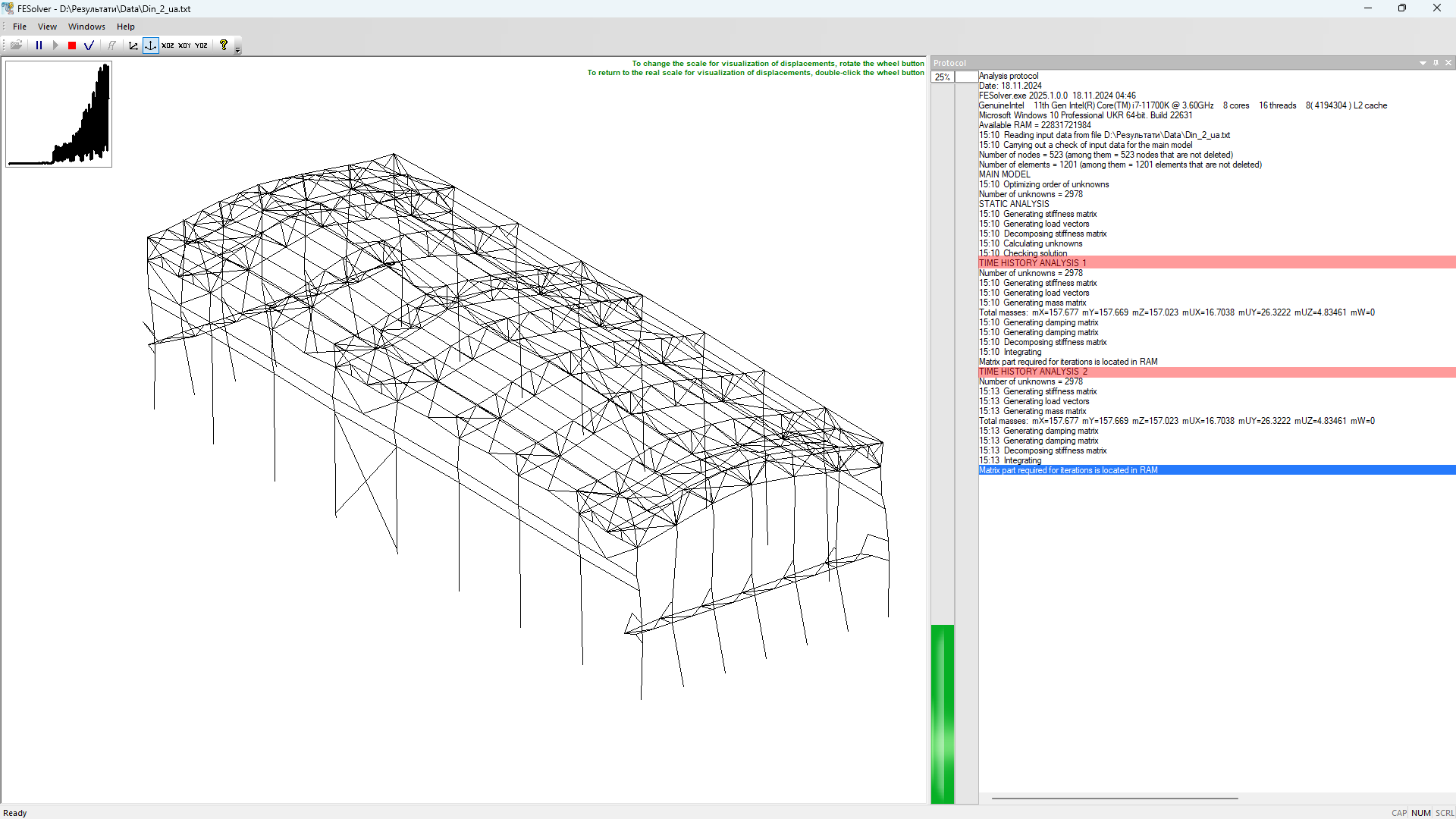
New type of stiffness for plates ' user-defined elasticity matrix.
For the spectral method of earthquake analysis, the damping ratio of mode shapes is calculated through the damping matrix.

New option to check the value of min percentage of contribution to modal masses to consider the mode shapes of natural vibrations in dynamic reaction of earthquake loads.
When you check parameters and analyse the problem, there is a new option that enables you to ignore in analysis the parameters of step-type process for solution of nonlinear problems, problems of assemblage-disassemblage of a structure, problems with progressive collapse, problems of engineering nonlinearity 1 and 2. This option can be used for preliminary high-speed calculations; in this case the data on nonlinear history/assemblage should not be deleted. When the "Ignore (in analysis) parameters of nonlinear histories/assemblage" option is selected, the analysis is performed on the specified load cases as analysis of a standard problem.
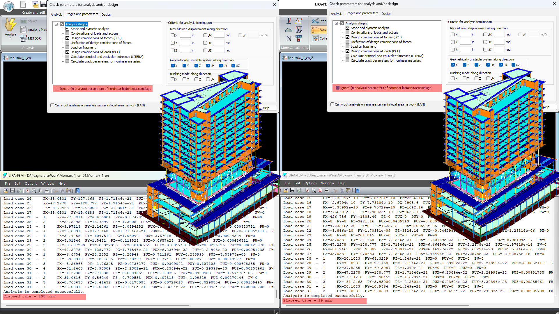
The Check parameter for analysis and/or design dialog box is modified; the analysis by solver of previous versions is excluded
For dynamic analyses in case of displacement of nodal masses, it is possible to define the masses of which directions should be moved.
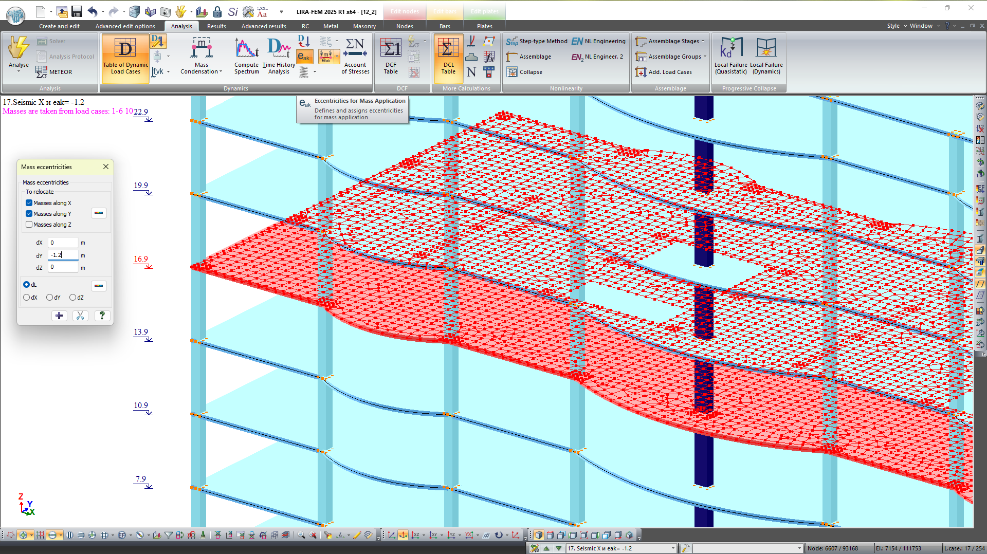
The option to consider the Rayleigh coefficients for earthquake analysis by the method of decomposition by mode shapes of natural vibrations.
To calculate the subgrade moduli C1/C2 and to calculate the pile stiffness, there is an option to exclude from iterations the loads that are not considered in clarifying the active pressure on the soil Pz.
New option to determine forces in bar analogues (BA) for load cases defined "by formula" (load cases created as a combination of analysis results of an arbitrary set of other load cases)
An algorithm is implemented to recalculate the original accelerogram to a specified height elevation different from the test measurement level.

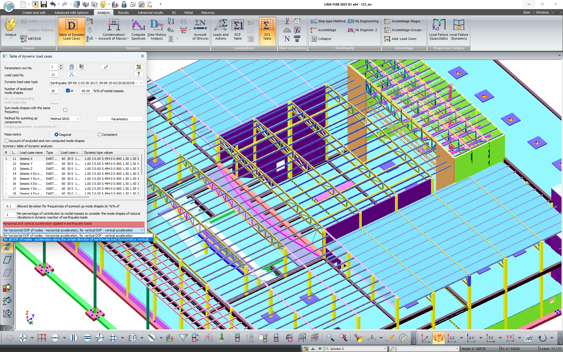
An optional way of applying horizontal and vertical accelerations in earthquake analyses has been implemented. Many seismic building codes have a separation between horizontal and vertical acceleration. Previously, in the same component of the same earthquake load, horizontal acceleration was applied to horizontal degrees of freedom (DOF) of nodes and vertical acceleration was applied to vertical degrees of freedom. Now optionally, if it is a horizontal load, then horizontal acceleration is applied to all DOF of the nodes, and if it is a vertical load, then vertical acceleration is applied.
Steel structures
For steel elements, the local stress resulting from concentrated loads may be considered according to EN 1993-1-1:2005/AC:2009. Also, an extended method of buckling analysis of the one- and two-sided stiffeners for box and I-sections is implemented.

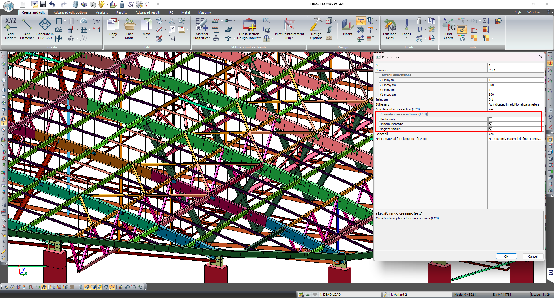
The new version implements a new optional way of classifying steel sections by local buckling according to Table 5.2 of EN 1993-1-1:2005/AC:2009. It is now possible to consider the partial or full plastic behaviour of the cross-sectional elements (distribution type ψ and α), whereas in earlier versions only the elastic stress distribution was taken into consideration. In this case, the forces Ned may be limited, and/or Ned, Med uniformly and proportionally increased until fyd is reached.

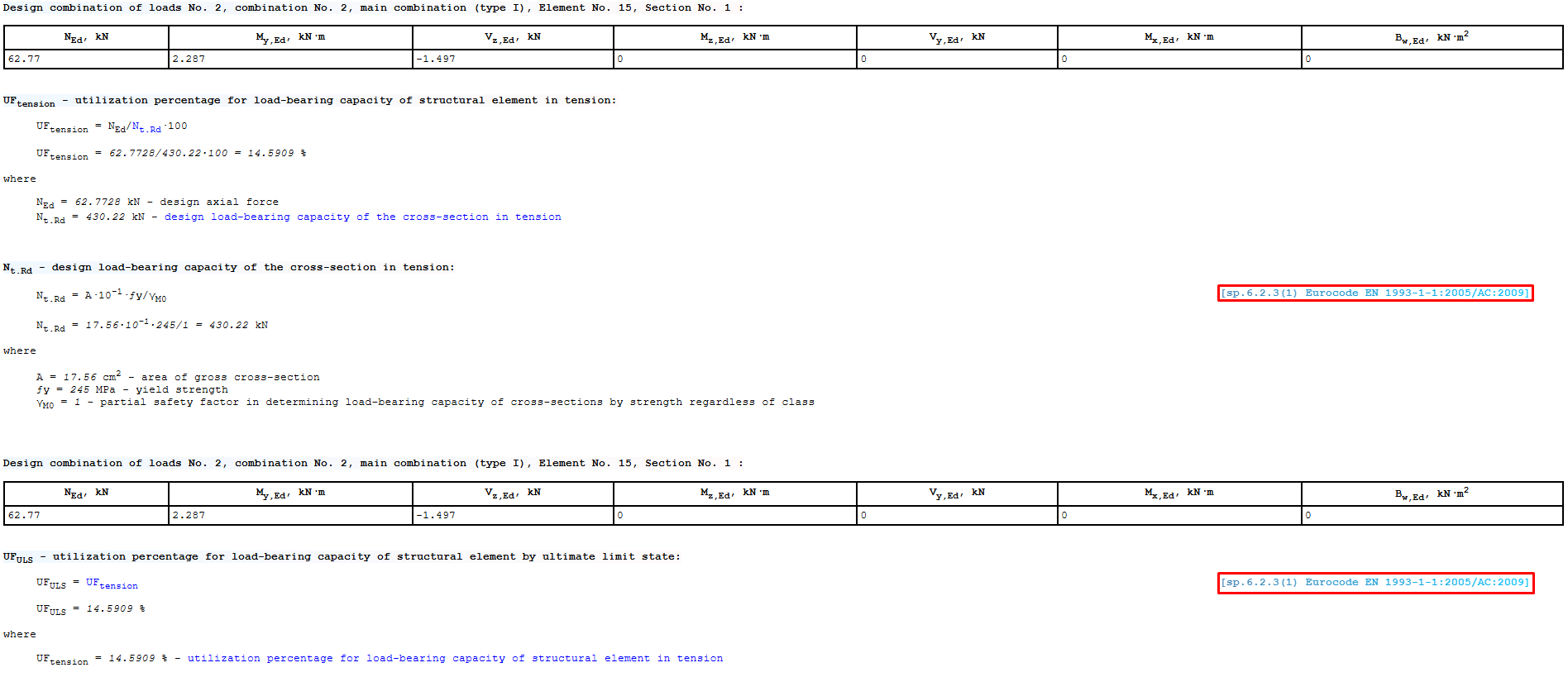
The tracing routine now includes references to normative documents used in the analysis. Additionally included are mosaic plots for errors based on EN 1993-1-1:2005/AC:2009. The user can comprehend the causes of unfavourable analysis results thanks to these plots.
Beam analysis with regard to the defined fixities is implemented, so in the overall stability analysis, it is possible to automatically divide the structural element into sub-elements.

For the element type Truss, the effective length may be defined and torsional buckling may be considered.
For the Single section type of unification, the restriction on the selection of steel sections is removed.
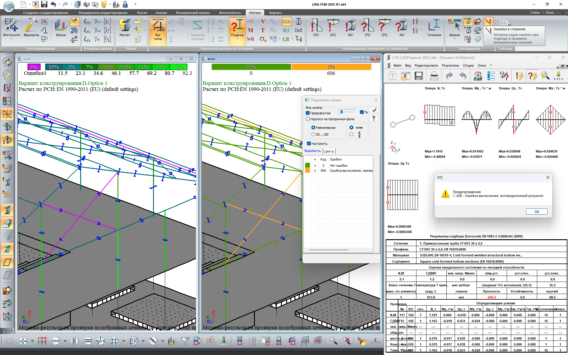
To identify errors that arise during the selection and check of metal sections, a new tool is developed. The design process is greatly accelerated by this tool, which helps the user locate and remove the errors.
For EN 1993-1-1:2005/AC:200, it is possible to check/select C-profiles with a rolled thickness of at least 4mm.
In the Metal analysis dialog box, it is now possible to define analysis of either all elements, or only elements selected on the model, or only elements included in the currently visible fragment of design model.
Additional functionality
Beam
A beam can now be modelled as a bar or plate element. In the new version for beams modelled as plates, it is now possible to specify the design location of the plate - vertical or horizontal. When the analytical representation for the beam is defined as a plate, the Bar Analogue option becomes available.
In the Beam properties dialog box, the parameters for snapping the element relative to the grid line are extended; they include the physical location of the cross-section and the location of the analytical bar. These parameters are now also available in the Filter by parameters and Select by criteria dialog boxes.
Optimised behaviour of the beam in the mode of manual editing of the analytical model; it includes the option to divide the beam into several fragments.
Partitions
R search and L search parameters are added to the object properties. In some cases, when a partition physically rests on a slab, the analytical model representation shows the partition as a linear load and the slab as a plate. If the Align Analytical Model property for the slab is defined as Auto, it can cause that the segments of the analytical plates of slab are shifted to plates of walls or bars of beams. As a result, the load from the partition may not be applied to the slab.
To avoid this case, the added parameters R search and L search ensure that the load is correctly distributed in the described situation and is properly applied to the structural object.
Piles
The program has been updated to provide a manual mode for altering pile models. With this mode, you can shift the pile analytics' location for more precise positioning and separate the pile's analytical bar from its actual volume. This enhances the quality of the FE mesh generation for the beam grillage. It is also possible to consider the influence of the foundation slab's punching shear beneath the pile action.
Grid lines
Previously, if the grid lines belonged to a specific storey and only the current storey was displayed, the grid lines became invisible as they could be on a hidden storey. Now it is possible to enable visualisation of grid lines across the entire building; in this case the grid lines remain linked to their storey. This is particularly useful for IFC import, where the same grid lines may be duplicated on each storey. In LIRA-CAD module, such duplicates can be removed, and thanks to the new setting the grid lines will be correctly displayed in certain views.
Staircase
The weight of the stair treads is now also considered when modelling the load from the dead weight of the structures. This allows for more accurate modelling of the load from these structural elements.
Opening / Door and Window Opening
New options to copy and transfer openings between projects and buildings. For convenient work with openings, their dimensions may be visualized in 3D model. These dimensions are also represented as additional objects that allow you to select the opening when you click on it. This option may be defined in the Filter for object visualization dialog box. It is especially helpful when you work with the model in the top view mode.
Shaft
The main purpose of shaft - is to create openings in slabs that intersect with volume of the shaft. Shafts can be generated either in the physical representation of the model or in the analytical one. In the analytical mode, the shaft contour can be 'magnetized' to analytical plates (walls and slabs), as well as to analytical bars (beams and columns). So, the required openings may be generated more accurately and quickly on several typical storeys at once.
However, the inter-storey staircases are often included in the shaft volume. To ensure that they are correctly represented in the model and are not cut out of the slabs by the shaft, a special property is added to exclude the influence of the shaft on such zones.
Object properties
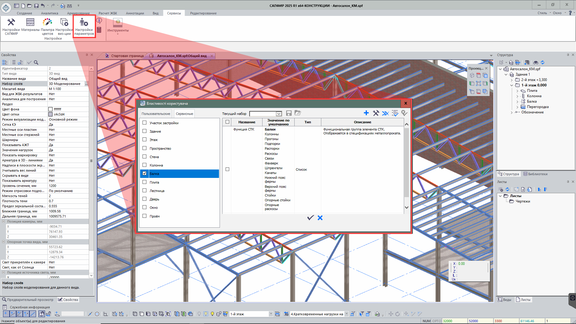
New tool Additional Properties of Object that allows users to create and manage additional parameters for objects of the model. These parameters provide more detailed control over the model and adapt data to specific project requirements.
The dialog box of this tool displays both custom parameters and standard object properties; it simplifies the data management and provides convenient access to all necessary characteristics in one place.
Linking parameters
The Link parameters of objects function is mentioned to establish a link between similar objects (column, beam, slab, inclined slab, wall, openings in walls, spaces and stairs) based on a selected parameter or group of parameters. The first selected object becomes a base object. It serves as a reference for other objects (followers). Objects may be linked by any parameter available for the selected object, including geometric location, dimensions, material and other parameters. Changes to the parameters of the sample object are automatically applied to all linked follower objects, ensuring data consistency. Additional tools allow you to see by which parameters the objects are linked and visualize the created links in colour. This option reduces the risk of errors and allows you to focus on more complex tasks, trusting routine changes to the software.
Modifying the contours manually
New option to edit manually the contours for Capitals and Column bases. Now it is possible to select capitals or column base as a separate object with its own set of parameters.
Tool: Create by sample
The Create by sample tool allows you to create new objects based on information about existing project elements. This tool greatly simplifies and speeds up the modelling process.
How the tool functions:
For example, if you want to add a column on the 4th storey and a column with the required parameters already exists on the 1st storey, you can select this column and activate the Create by sample command. The program will automatically switch to the mode of creating a structural object with similar properties.
Customization:
Once the command is activated, the user could change any parameters that have been transferred from the selected object. This allows you to minimize data entry and focus only on modifying key parameters.
Benefits:
- Simplify object generation: To add elements quickly based on the elements available in the model.
- Reduced risk of errors: To auto copy parameters; it reduces the incorrect data entry.
- Speeding up the work: To reduce the time required to generate a model.
The Create by sample tool provides accuracy and convenience when creating new elements and duplicating elements; it speeds up the process of model generation.
Tool: Twist angle of the beam section along the trajectory
This tool allows you to model the behaviour of a structure more accurately. The tool takes into account the physics of beam twist along its axis; it is especially important when in analysis of complex 3D structures.
The twist data is not only visually displayed in the model, but is also correctly taken into account when the whole object is divided into finite elements for analysis.
Transfer of project description from LIRA-CAD to LIRA-FEM
In the new version of the program, it is possible to transfer the project description from LIRA-CAD module to LIRA-FEM program. The project description, which is not usually reflected in the project title, can be defined by the user in the project's properties. Now the user could record the data describing the specific features of the object and other important data in LIRA-CAD and transfer it together with the project to LIRA-FEM.
Loads
The following loads can be generated:
- Impulse load at nodes and along the line. For the load, the following data should be defined: load case, load value, load direction, pulse shape, duration of load, period of repetition of the load and number of repetitions of the load. The load may be automatically snapped to the structural object of the building.
- Harmonic load at nodes and along the line. For the load, the following data should be defined: load case, load value, load direction, load diagram, load amplitude, phase shift. The load may be automatically snapped to the structural object of the building. For correct analysis of the dynamic load "Harmonic (24)", a full set of necessary parameters is provided, including the inelastic strength factor of material and the forced frequency of the external action, as well as taking into account the frequencies preceding the specified one.
New types of loads may be created: pyramidal load (property of Surface Load tool) and load from the weight of the coating on the object surface (property of Special Load tool).

It is possible to copy loads from one load case to another, including with a scaling factor. It is also possible to copy load case together with loads. In the Load Editor dialog box, there are options to display loads by area in colours according to their intensity for one or more selected load cases. An option to revert the loads to the load colours is also provided.
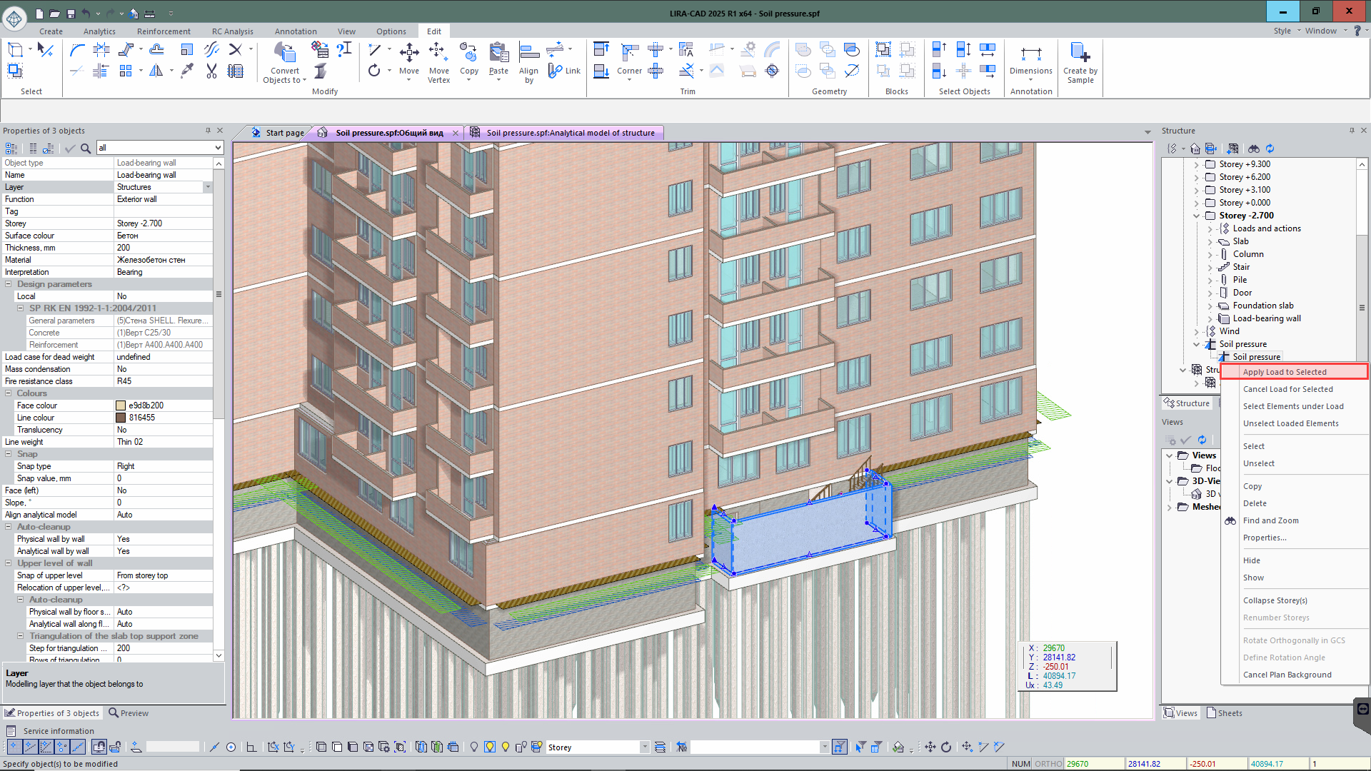
You could manage loads (assign, remove loads and select elements that this load is applied to) from the Project Structure window. It is available for load types: Special Load, Soil Pressure and Ice Load.
Ice load
The tool for collection of ice load is substantially improved:
- Support for building codes: DBN B.1.2 - 2006, NP to SP RK EN 1993-3-1:2006/2011, SNIP 2.01.07-85;
- To collect ise load to the Rope element with account of regulatory documents;
- To collect ise load on structures above 100 metres, with account of regulatory documents;
- To generate the ice wind with account of regulatory documents.

Wind load on the roof
In addition to automatic wind load collection for flat, shed and gable roofs, wind load may be collected from the vaulted roofs in accordance with DBN B.1.2 - 2006 and EN 1991-1-4 is implemented.

Node: Explosion
Node Explosion is mentioned to automate all processes related to the determination of the explosive load intensity and its application to the relevant structural elements, taking into account various explosion parameters (mass of the charge, explosion position (in the air or on the surface), the step for approximation of the overpressure distribution function, the load case No., etc.). Overpressure on structural elements is calculated according to the international standards (UFC 3-340-02: Structures to Resist the Effects of Accidental Explosions). The load can be applied both statically and dynamically. In the latter case, the program automatically generates graphs of the time impact of the impulse.
Note:
When calculating the load intensity, the current version of node does not consder aerodynamic coefficients.

Special load
The Special Load element is mentioned to model pressures of liquids and gases on tank walls, as well as other loads distributed over the area of plate or bar elements. This tool provides realistic modelling and helps the user consider external actions on the structure.
Features and usage:
-
Apply to the elements of the model:
To assign a special load to specific elements or groups of elements, select the Special Load object and the appropriate elements of the model.
-
Multi-level arrangement:
The special load is added to the level of the active project, so it may be applied to elements located on different storeys of the model. This simplifies work with loads in complex projects where elements are distributed on several levels.
-
Generate elementary loads:
When creating a meshed model, each Special Load is converted into a set of elementary loads. The parameters and method of application of these elementary loads depend on the settings for the Special Load object.
-
Verify visually in analytical view:
The distributed loads can be visually verified in advance in the analytical representation of the model; it enables the engineer to confirm that their application is proper prior to analysis.
The use of Special Loads in the LIRA-CAD module makes it possible to effectively take into account complex loads on the structure, ensuring high accuracy of modelling and analyses.
Space load
In the Space contour tool, with the Interpretation option indicated as the Load, it is now possible to apply loads to the following objects: inclined slabs, slabs with variable thickness and stairs.
Moreover, in the new version for this element, there is an additional set of checkpoints displayed at the top of the space. This greatly simplifies and speeds up the process of modifying the space contour.
Auto snap the load to the element
The new version of the program introduces the Load Snap option that allows you to automatically snap a load to a structural element. Before placing the load in the model, the user can activate the Snap command and then select the structural element to which the load will be attached. Then the load attached to the certain object is generated.
Example:
If you design a metal frame where the purlins are supported by main beams, the roof weight can be defined as a linear load along the purlins. If the step of the purlins is changed, the appropriate load will automatically update its location to match the new location of the elements.
Benefits:
- Accuracy and reliability: The load is always linked to the relevant structural element.
- Auto update: When the layout of the elements changes, the load adapts automatically without the need for manual modification.
- Simplifying the modelling process: The function reduces the probability of errors and ensures that the model is generated correctly.
This feature improves the usability and accuracy of the design procedure by automating the work with loads and minimising the risk of errors in case of modification in structure.
Load cases (dialog box)
The following options are added:
- to generate data for subproblems, collect masses, and perform stability analysis;
-
to perform a number of operations via the shortcut menu, including:
- to define dynamic loads (mass collection);
- to colour loads by colours of load cases;
- to colour loads according to their intensity;
- to define parameters for load cases;
- to copy loads from one load case to another.
Analytical model
Subproblems
New technology to define the input data for the Subproblem method. With this technology, many independent sets of subgrade moduli and sets of coefficients to modulus of elasticity can be used in a single design model.
Each loading stage may have a different set of parameters based on the subgrade's properties or maintenance conditions. Therefore, the soil's heterogeneity and the unique features of the foundation-structure interaction may be taken into account; this allows for a more realistic description of the system's actual conditions.
Furthermore, the flexibility to assign different coefficients to the modulus of elasticity at every stage of analysis creates additional opportunities for more precise design solutions.
Input data for the stability analysis
In the new version of LIRA-CAD module, it is possible to define the input data for stability analysis of structures. Users can define key parameters and select objects for analysis. Main options:
- To select the calculation method: by forces or by DCLs.
- To define load cases: either loads or DCLs to be considered in the analysis procedure.
- To include elements in the analysis: in the properties of objects you could define whether they are considered in stability analysis.
The defined parameters are automatically transferred to LIRA-FEM. So, it eliminates the re-entry of data, reducing the risk of errors and speeding up the modelling and analysis process.
Condensation of masses
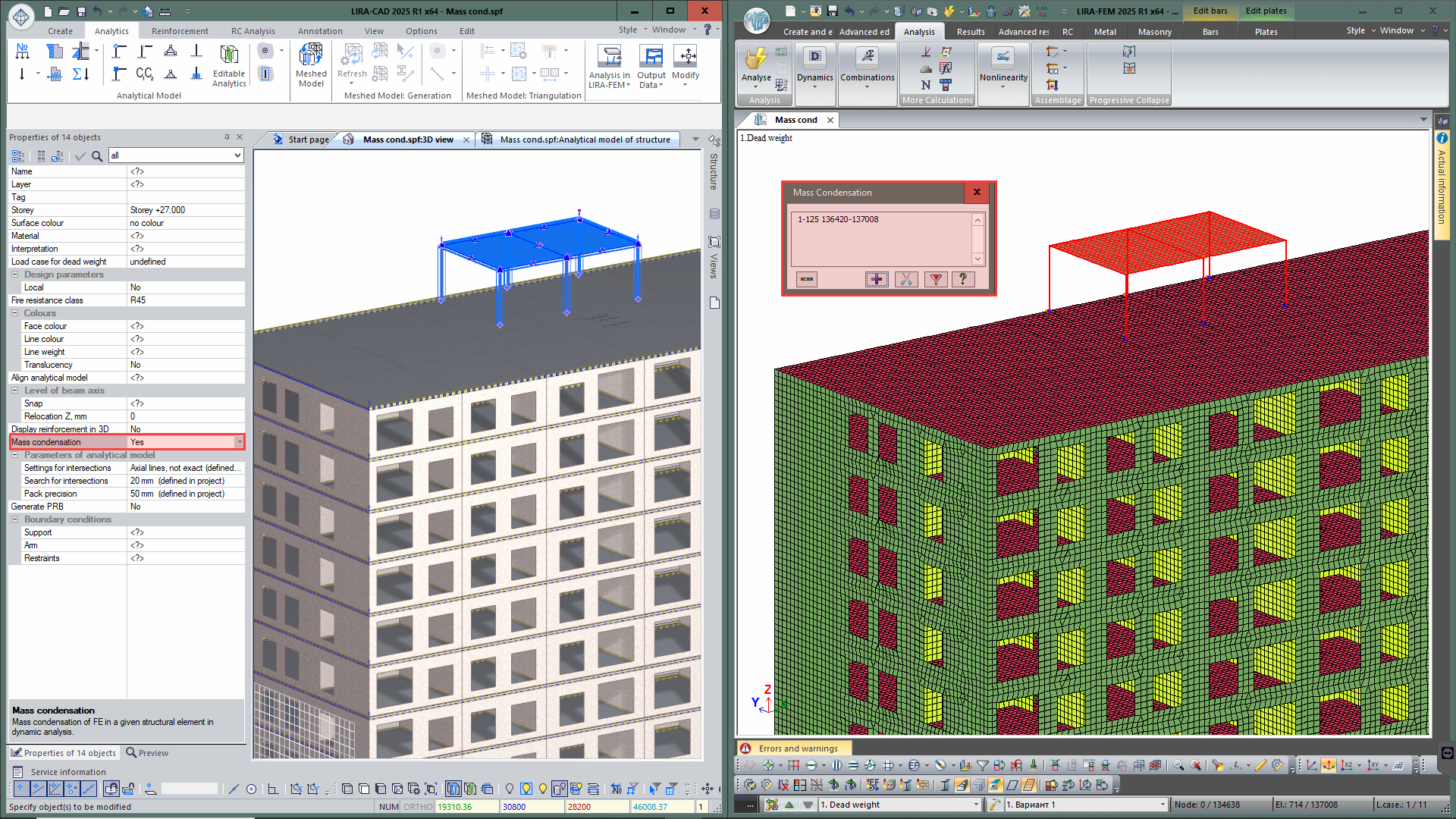
New option to define the Condensation of masses to optimise dynamic analyses, especially when analysing vibrations of structures. Only masses of the main structure are considered when searching for mode shapes, while the masses from the flexible part (masses of selected elements in which natural vibrations are not of interest to the user in this problem) are concentrated in its support nodes (support nodes of selected elements). Also, it is now possible to perform Selective account of masses in elements to consider exactly the masses of selected elements for dynamic analysis.
Unification of bars
New option to preliminary unify bar elements (beams and columns) for analysis of reinforcement or metal sections. In the Unify bars dialog box, all elements of the model are listed: columns, beams, as well as elements of trusses and beam systems. The table contains data about name of the element, its length, section and material. Unification can be performed on the basis of tags assigned to elements, or unified groups of structural elements (UGSTE) can be created. A graphic presentation of elements by tag colours is available now. Unified groups (created on the basis of tags or assigned to UGSTEs) can be transferred to the VISOR module of the LIRA-FEM program.
The unification table in its current state can be placed on the drawing as an editable table. You can also export its contents in TXT or CSV formats for Microsoft Excel.

Perfectly rigid bodies (PRB)
In previous versions of the program, there was an option to arrange the combined behaviour of beams and slabs with the Offsets tool that provides a reliable connection between elements. In the new version, an additional option - Perfectly rigid bodies - is added, providing an alternative modelling strategy.
The length of the PRB is determined automatically based on the distance between the analytical models of objects and is updated in real time when any of them is moved. In the analytical representation mode, the PRB model more clearly demonstrates the interaction between the slab (plate) and the beam (bar).
With this approach, the interaction between beams and slabs can be described more precisely and adaptably, ensuring that they behave together as a single system. The use of Perfectly Rigid Bodies extends the functionality of the program, offering a new way of modelling such connections and increasing the accuracy of calculations.
Triangulation
Triangulation regions in the slab above the walls are updated when the walls are moved or modified. New option to update the dimensions of an existing triangulation zone and the step of approximation of its contour lines. In previous versions, it was necessary to delete the old triangulation zone and create a new one with updated parameters.
Triangulation points in the slab above/below the walls are created automatically for flexible customization of triangulation mesh. To manage the triangulation points, use the following parameters: step of triangulation points and number of rows. You can also specify the number of rows with fixed step of triangulation points. In this case the remaining rows will have a transitional step of triangulation points. The value of this transitional step can be in the range from fixed step to user-defined step of triangulation in the plate.
Additional grid of triangulation lines
To improve the accuracy in modelling of slab triangulation zones, a new tool Additional grid of triangulation lines is introduced. It allows the user to define the cells by which the slab is divided into finite elements, providing more detailed modelling.
Key options:
- To define parameters for the cell: The user specifies the dimensions of the cells to be used for triangulation.
- To select the triangulation zone: Define the slab on which the additional grid will be created.
- To define the generation method: Depending on the needs of the project, you can select different shapes for the additional zone: rectangle, sloping rectangle, inscribed or circumscribed polygon.
- To locate the additional zone: The tool allows you to place triangulation zones at key locations to create a denser and more accurate FE mesh.
Benefits:
- Easy to set up and use: The tool is intuitive and easy to set up.
- Visual clarity: The user can immediately see how the future triangulation mesh will look like.
- Modelling accuracy: Provides optimal densification of finite elements in important zones of the meshed model, improving the quality and accuracy of the analysis.
This tool simplifies the creation of complex meshes and allows for precise control of the finite element structure, especially in critical parts of the model.
The Pit
A new object - a Lift Pit is automatically created on the basis of an opening defined in the foundation slab, and its dimensions depend on the dimensions of this opening.
The pit has a set of Slab and Wall parameters that can be modified parametrically (thickness, boundary conditions, interpretation, etc.). For the walls of the pit, it is possible to define a thickness variable in height.
To select the analytical representation of the pit walls, use the parameter Create walls - Yes/No:
- Create walls - Yes - the walls and the slab have an analytical representation of the Plate;
- Create walls - No - the plate has an analytical representation Plate, the walls are replaced with an Offset.

The Plate tool
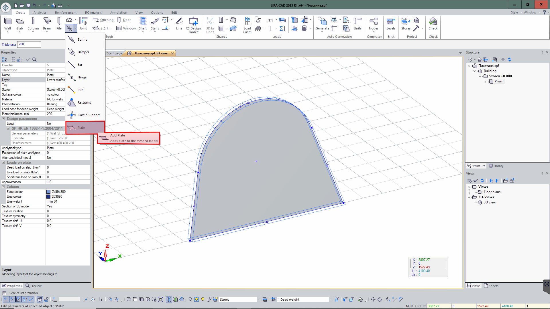
In addition to the already available special elements such as Free Spring, Damper and Bar, a new tool is added - Plate. This element has all the standard properties of the Slab type element, but its functionality offers a more flexible approach to introducing flat elements into the model.
The Plate tool allows you to generate elements that can be 'magnetized' to the checkpoints of other objects in any way. This generation method greatly simplifies the process of integrating an element into complex structures and offers more precise location in the model. With the help of this tool's versatility and user-friendliness, engineers may effectively build complicated systems by taking into consideration the geometric and structural properties of other elements in the model.
Cable-stayed structures
There is now technology to define the input data for modelling of cable-stayed structures. With this technology, a unique product called Rope can be created. For this element, it is possible to define key parameters necessary for accurate modelling of such structures:
- Type of section , with the rope profile indicated;
- A method for dividing an element to consider its geometric and design properties;
- The tension; so, the stress in the structure will be considered properly.
For complicated cable-stayed systems, including stadiums, roofs, bridges, and other structures with tension elements, this component offers more precise and effective modelling. With this method, the modelling of objects with unusual features is optimised and the accuracy of design solutions is increased.

The Project Template
The Project Template tool is mentioned to simplify the creation and management of projects (documents). Users can create templates either on the basis of existing projects or from scratch, adapting them to specific tasks and requirements.
Project Template options:
-
To preserve the project structure:
The template captures the structure of the project, including the storeys and all the elements placed on storeys; it allows you to quickly reproduce certain configuration.
-
To customize the project parameters:
The template stores key parameters required for the design, such as the applied building code and settings for the meshed model.
-
Load Editor:
The template includes preset load cases and their settings, DCF and DCL parameters; so, it is possible to avoid repeated data entry and improve efficiency.
-
A variety of templates for different tasks:
Templates can be customized for different types of projects, such as metal or reinforced concrete frames, including parameters for creating the PRB, element connections, triangulation step and other parameters that should be considered when modelling a building.
-
To adapt the templates for the building codes:
It is possible to create templates for analyses by different building codes, while keeping all the necessary parameters.
-
Default template:
The user can assign a template that will be automatically applied to all new projects; it speeds up work and minimises errors at the start of the project.
Advantages of templates:
The unlimited number of templates allows the user to customize the templates for different requirements. It speeds up the generation of models, reduces errors and eliminates repetitive data entry. This approach makes the design process more efficient and accurate, especially when you work with typical projects.

Updated graphics engine
The graphics engine in LIRA-CAD 2025 has been updated to support OpenGL 4.6 graphics. It allows for greater compatibility with graphic equipment from various manufacturers and enhances visualization of designed objects.
- The speed for model rendering is increased. Now when you change the view, rotate or perform other actions with the model, the screen refreshes 7-10 times faster compared to previous versions.
- The quality of textures, labels, texts and lines is improved.
- Visual effects of falling shadows, relief surfaces, fog and diffuse shading are implemented.
Rhino (Grasshopper) Plug-in improvements
Adaptation of plug-in for integration of LIRA-CAD 2025 and Rhino 8 (Grasshopper)
Adapted plug-in for two-way integration between LIRA-CAD 2025 and Rhino 8 (Grasshopper). This technology allows not only importing complex geometrical shapes from Grasshopper and converting them into LIRA-CAD structural objects, but also performing reverse data transfer. LIRA-CAD structural objects can serve as a basis for creating geometry in Grasshopper; it allows the user to take into account the real location of structural elements and use their geometry for accurate modelling of additional parts of the building in Grasshopper.

Interaction between LIRA-CAD module, Rhino, Revit and Archicad
Interaction between Rhino 8 (Grasshopper), Revit (Rhino.Inside.Revit), Archicad (Archicad Live Connection) and LIRA-CAD (Generator) is supported. It allows you to work with a single model and ensure data consistency at all stages of design.
New plugin features:
-
SapfirUpdate
With this node, you can only update the model in LIRA-CAD when requested, which is useful for large projects where frequent updates can hinder efficiency.
-
LoadPnt2
This node generates concentrated loads with a specified direction and intensity determined by the mutual location of two points. The load is generated between the appropriate input points, and the load value and direction depend on the distance between them.
-
LoadArea
Node for creating a non-uniformly distributed load with the option to define an arbitrary contour and taking into account the openings in the load zone.
-
LoadLine
The load allows you to define linear loads with controlled vector direction. The load can be non-uniform and the angle of application is controlled by the direction vector. You could define the objects that the load will be applied to.
-
LoadPnt
Node for specifying point loads, where the user defines the coordinates of the point at which the load is applied to, the direction of the load vector and the load value.
Generator improvements
New nodes are added to the Generator system to extend its functionality:
-
New node Objects in project: stores complete information about all objects in a project, facilitating data management at all stages of design. It allows you to quickly find and select elements by specified criteria such as type, properties or location.
 Node 'Objects in Project'
 - Concentrated load at point: node allows you to specify point loads at specific locations in the structure. The user can define not only the coordinates where the load is applied to, but also define the direction of the load using a vector and define the load value.
-
Generate linear loads by the specified load: this node implements the process of determining the required load intensity and application of loads to objects. The user can specify the line along which the load will be distributed and select the elements, such as bars, that the load will be directed to. For accurate modelling, the direction of load propagation can be adjusted by specifying the appropriate vector.
Once all parameters are defined, the load is visually displayed on the model. So, the user could verify that the load is applied correctly and make any required modifications. - Contour fragmentation: node splits (cuts) a complex closed contour into square contours in which the side is equal to the specified fragmentation step. This tool is especially useful when you need to approximate curved contours for further evaluation or processing.
-
Advanced generation of storeys by height and number: this node provides flexible tools for modelling the storey of a building with account of the height and number of storeys. This feature is very popular with users who have called for its further development. All of this information is now simply contained in a single node, eliminating the need to enter other nodes that were previously used to indicate the number of storeys and their heights.
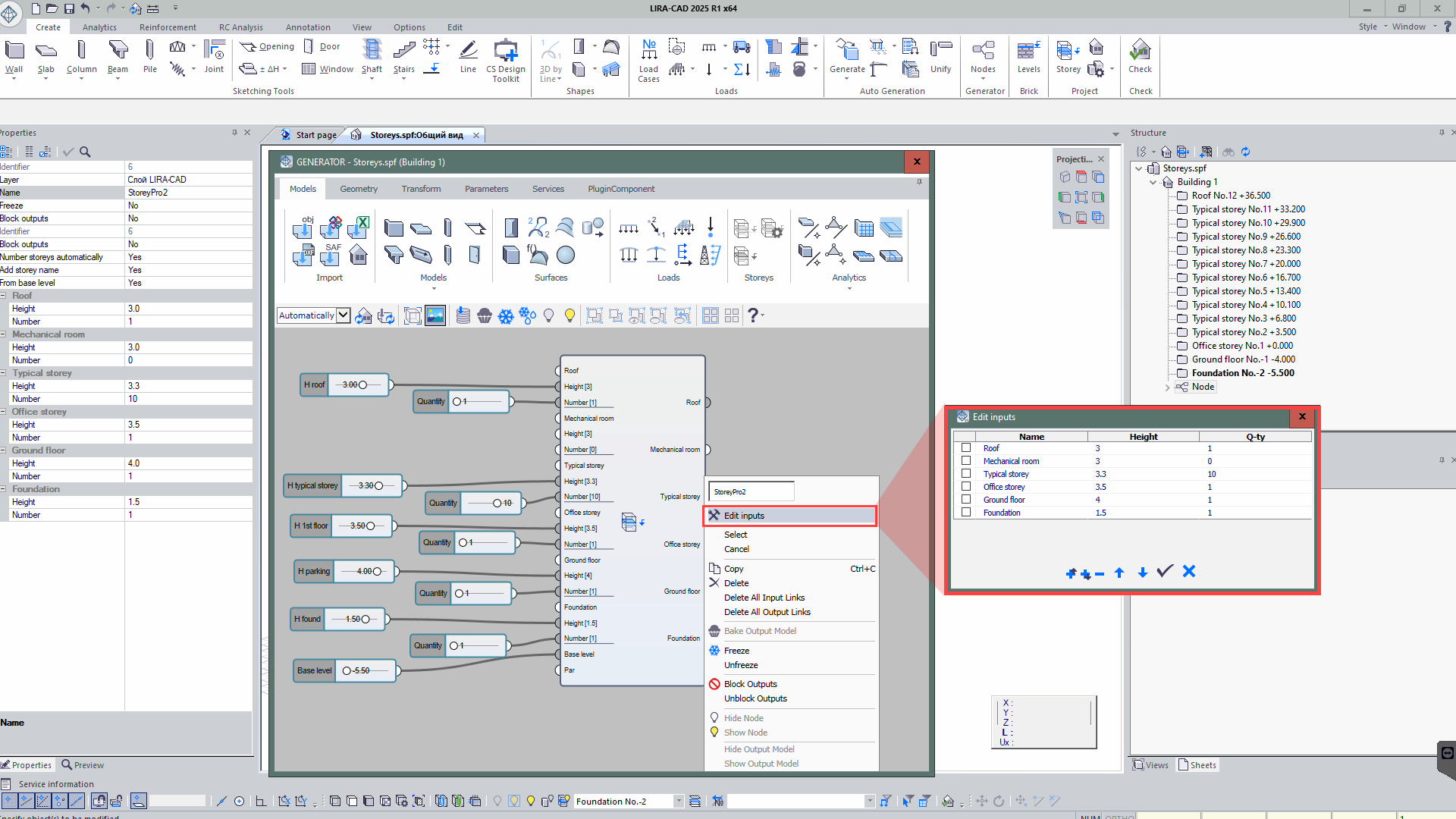 Node 'Generation of storeys'
 -
Compute the centre of mass and normal vector of a contour: this node provides the option to compute the centre of mass and normal vector for contours.
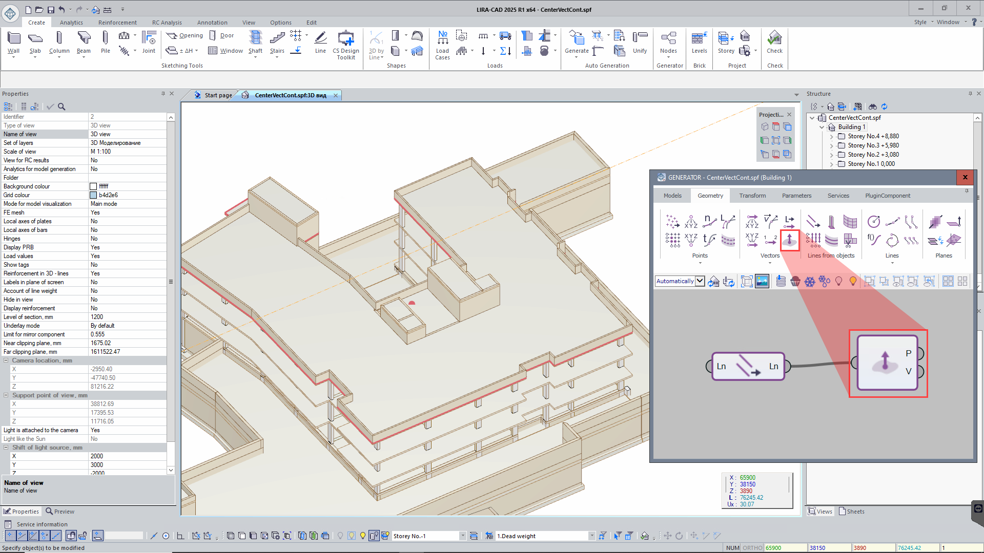 Node 'Compute the centre of mass and normal vector of a contour'
 - Extended functionality of the Block of nodes: now it supports nested blocks, allowing you to place one block inside another.
- Vector product, angle between vectors: this node extends the options in working with vectors, allowing to perform additional mathematical operations. In addition, the option to calculate the angle between vectors allows you to evaluate the relative orientation of elements in space.
- Function graph value: this node is mentioned to calculate function values at specified points based on the provided graph. It allows you to obtain Y values for certain X values based on the specified data. When this node is applied, the user could efficiently obtain function values at arbitrary points; it is especially useful when you need to interpolate or extrapolate between known points.
- Generate segments between all points of array P0 and array P1: this node automates the process of creating segments between sets of points; it allows you to connect each point in array P0 to each point in array P1. This greatly simplifies the generation of complex geometric structures where many points should be connected to each other.
-
New node Tunnel: solves the problem of confusing links in complex models by providing a 'wireless' way to transfer data between elements. Links are created automatically based on matches in key names, simplifying the model structure and making it easier to work with elements that are far apart on the canvas.
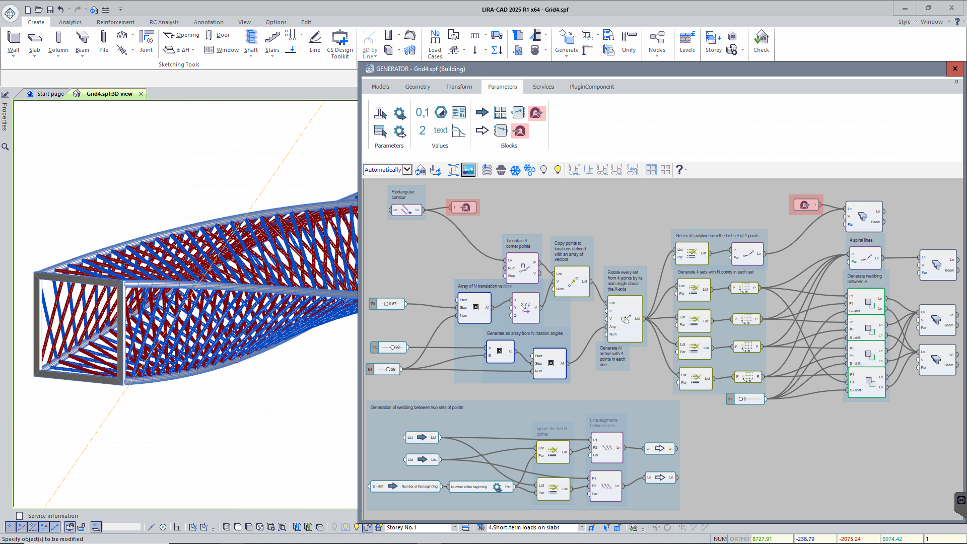 Node 'Tunnel'
 -
New node Multiplexer: optimizes the work with variant models, allowing you to create and manage multiple design options in a single project without duplicating files.
- Fast replacement of design elements: it is easy to replace elements based on the line and the original object.
- Option to modify properties for elements that are of the same type: to work with one type of element, modify its properties in different ways.
- Easy variant management is possible because to the multi-layer technique, which eliminates the need to navigate between files to control and adjust parameters.
-
New nodes Crack in the slab and Crack in the wall: these nodes allow modelling damage/defects in building structures with special FEs. The user can define a line that follows the trajectory of crack propagation. Then adjust the step, stiffnesses, and UCS position for the special FEs to simulate the damage.
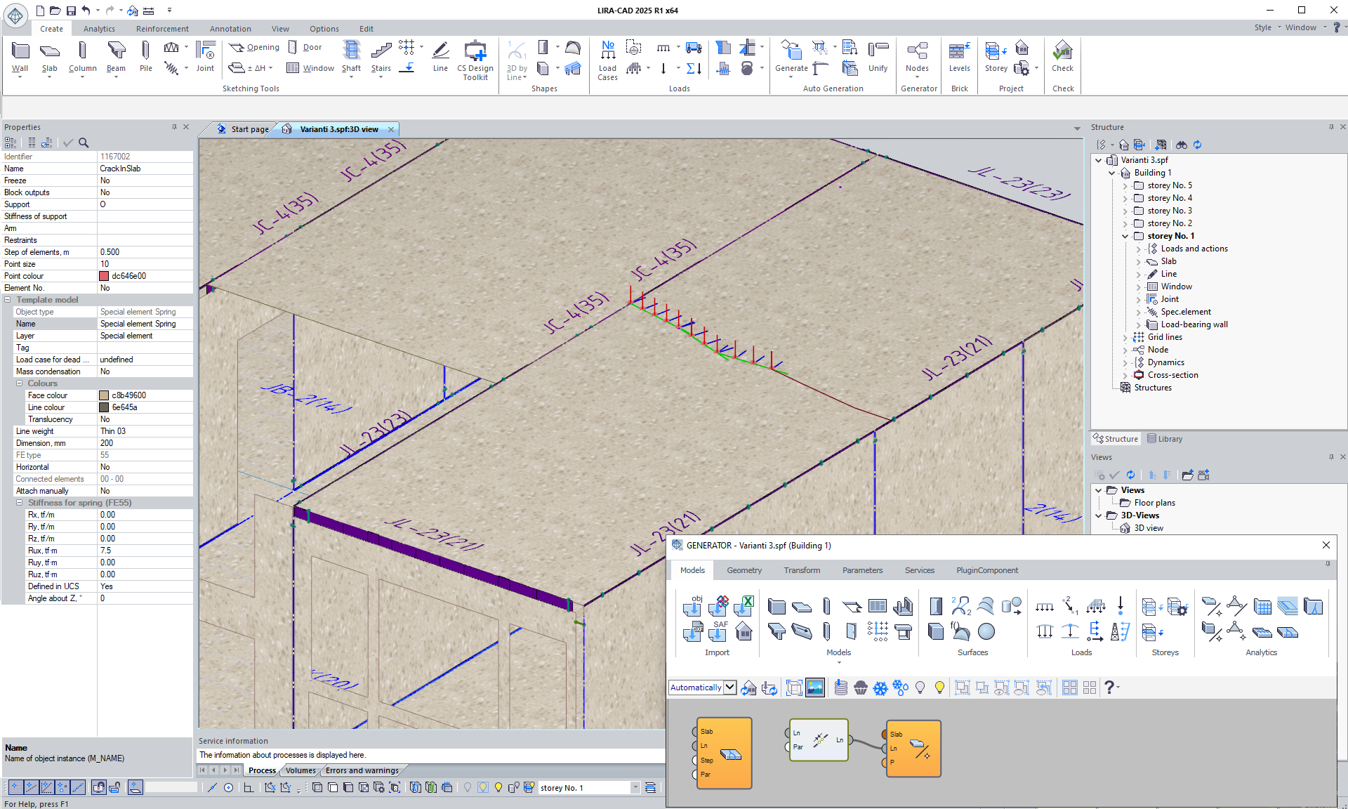 Node 'Crack in the slab'
 - The properties of the node Filter elements of specified layer: a convenient drop-down list with all model layers is now displayed instead of a dialog box. It allows you to select the required layer faster and significantly speeds up the work process.
- In the node of creating piles by points, it is now possible to select any cross-section from the LIRA-CAD library. This improvement allows more accurate modelling of the meshed model and reduces the need for manual editing when some parameters are missing in the nodes.
- In the node DXF/DWG Import files, there is now an option to group and split standard storeys. It allows simplifying and speeding up the input of structural objects if they are the same on standard storeys. When splitting, the flexibility to add structural elements with unique features to the storeys of the same type is preserved while ensuring the convenience and efficiency of working with this node. The underlay by storey mode will also automatically generate storeys based on the number of standard underlays in the file, as well as locate underlays on storeys and align storeys in the plan according to the specified base points.
- In the node Symmetry of objects relative to plane/line, the work algorithms are updated, and the model generation procedures employing its functions are optimized.
DWG export/import improvements
In the LIRA-CAD module, the DWG file import tool is greatly improved. The tool now enables you to generate new objects tailored for the LIRA-CAD module and more precisely modify parameters throughout the import process.
Users praised the previously created technology for importing DWG from a single file. To boost efficiency and convenience, this capability has been substantially enhanced in the latest release.

- Multi-layered drawings for a single storey:
In previous versions, all structural elements were located on one drawing, which occasionally led to crowded data. With the updated version, users can organize the structural components by category and produce many drawings for a single storey. For example:
- Separate drawing for the pile groups and foundation slab.
- Separate drawing for columns and walls.
- Separate drawing for beams and slabs.
- Advantages of the new approach:
This way of entering data makes the process more convenient and reduces the chance of errors. It is simpler to locate and modify the elements you require when they are divided by categories.
- Consistency with familiar design practices:
The new approach is closer to the standard technology of working drawings, where similar elements are displayed on separate sheets. This shortens working time, reduces the risk of errors, and makes the data entry process more intuitive without the need for retraining.
IFC improvements
Importing model to IFC format
The new LIRA-CAD module offers a more flexible and accurate way to define parameters for the work with IFC files. This greatly enhances the import process and data adaptability to project requirements. Users may now configure the correspondence between object parameters in IFC and parameters in the LIRA-CAD module. The settings can be applied individually for each type of objects, ensuring high accuracy of data transfer and correspondence.

Key features and improvements:
-
Import of the model with updating of all structures in the model:
Users can import the model to an existing building and replace the previous structures with the current version; it helps to synchronise the data at different stages of the design.
-
Import of several structures within the one project:
Import of multiple structures within a single project is supported; it simplifies the work with complex models and improves coordination between different design chapters.
-
Improved mechanism for conversion of objects:
An improved algorithm is implemented; it converts general-purpose objects into LIRA-CAD compliant structural elements, speeding up the data integration process.
-
Setting the parameters of materials and sections:
It is possible to specify material and cross-sectional parameters for each group of elements on an element-by-element basis. This provides greater flexibility in modelling and analyses, allowing the design to be adapted to specific requirements.
-
A mechanism to sort and evaluate data in the dialog box:
In the import dialog box now it is possible to sort columns; it makes working with huge amounts of data more convenient and makes data evaluation and correction easier.
-
Option to display the number of elements by groups:
There is a column with the number of elements that belong to certain groups based on materials or sections; it enables the user to quickly assess the scope of the project.
-
Flexible modification of additional parameters:
The import tool increases data transfer accuracy and facilitates collaboration with other project participants by enabling the user to set attributes such as IFC identifier, interpretation, tags, and names.
-
Improved mechanism for generation of storeys:
Updated algorithm for generation of storeys for imported buildings in case there is no information about storeys or slabs located at intermediate elevations between levels. This ensures correct generation of storeys and facilitates further work with the model.
Exporting the model to IFC format
The program exports the model to the IFC format that supports flexible configuration and permits the exported data to be modified in accordance with project specifications.
This tool provides the following options:
- To select the objects to be exported:
- all objects of the model.
- selected objects; it is convenient for transferring only individual parts of the project.
- selected and visible objects with account of the current view of the model on the screen.
-
Checkpoint snap of the building:
When exporting, you can set the exact coordinates of the checkpoint snaps for the building; it ensures correct positioning of the models in the general project and makes integrating with other applications and participants easier.
-
To customize the settings for the export:
The tool enables the user to flexibly select the parameters to be exported for each element. This includes geometric properties, physical properties, materials and other data important for an accurate description of the model.
-
To save the presets of the settings:
The presets for the export settings can be saved for easy reference. So, you could use the preset settings in the subsequent export operation, saving the time and reducing the possibility of configuration errors.
-
User-defined parameters:
The User-defined parameters tool allows the user to create a set of additional parameters that you can control during the process.
These parameters are also transferred to IFC format and can be integrated with other programs, ensuring full data consistency throughout all stages of the design process.
Tekla Structures Plug-in improvements
LIRA-FEM 2025 provides two-way integration with Tekla Structures 2024. The analytical model is exported from Tekla Structures 2024 to LIRA-FEM, while the selected reinforcement and updated finite element cross sections are imported to Tekla Structures 2024 from LIRA-FEM.
Autodesk Revit Plug-in improvements
Autodesk Revit 2025 and LIRA-FEM are integrated via a two-way converter. Thus, there is full data exchange between the programs. As a result, engineers can rapidly transfer and synchronise models, and it is possible to carry out complex analyses and design of metal and reinforced concrete (RC) structures.

Improvements in API and input tables
Expanded options to generate the model and get access to analysis results. Thus, you might use the API to generate your own modules. For example, generate complex objects, automate routine operations, and obtain information on architectural or design models so that the models can be transferred to other software and vice versa.

New input tables are added to define/edit the following data: arc grid lines; types of pilot reinforcement (PR) and their assignment to elements of the model; input data for dynamic load cases; selective consideration of masses in elements; eccentricities of mass application; loads; surface loads; loads on fragment; bar analogues; plate analogues.
Keep in mind that Input Tables can be used as an alternative way to define and edit data about design models, import data from other programs, and partially copy or update the model - through the user interface or programmatically, via COM technology.

Новости 21 - 40 of 49
First | Prev. | 1 2 3 | Next | Last