VERSION HISTORY
LIRA-FEM
- Components of BIM technology
- Generating and modifying the model
- Generating and modifying the design model
- Analysis options
- Tools for evaluation of object properties and analysis results
- Analysis & design of reinforced concrete (RC) structures
- RC Expert
- Analysis & design of steel structures
- Soil
- Cross-Section Design Toolkit
- Documentation improvements
Analysis Options
Enhancements to Analysis Capabilities
-
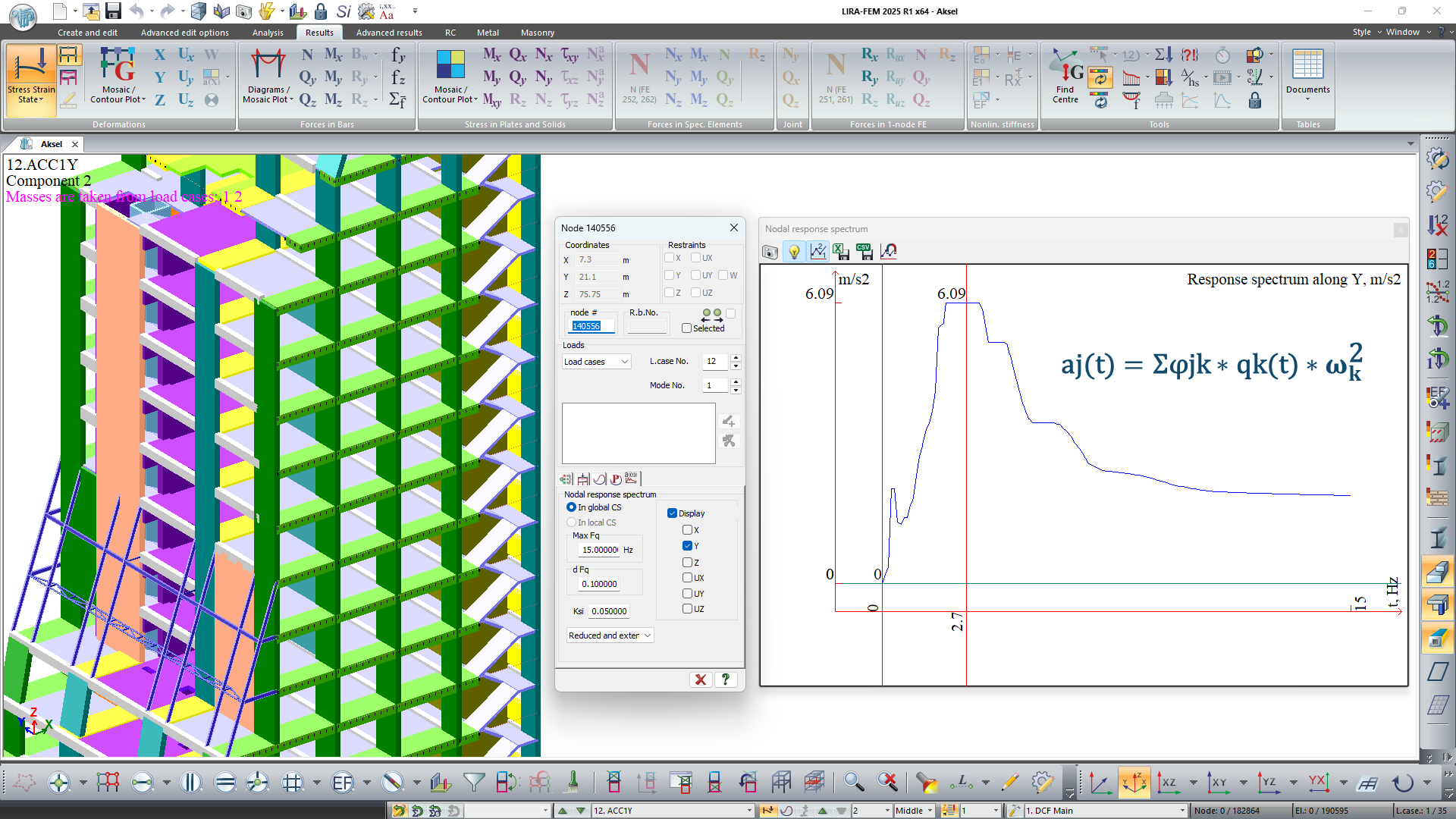
When generating response spectrum graphs using module 27, the approach for determining the final accelerationsЧtaking into account all mode shapes on which the spectrum is basedЧhas been adjusted.
Now the spectrum is generated based on the graph of pseudo-acceleration changes (floor accelerogram), where the acceleration at each moment is determined as follows:
aj(t) = ΣΔjk * qk(t) * ωk²,
where aj(t) is the acceleration of the j-th degree of freedom at time t,
Δjk is the ordinate of the j-th degree of freedom for the k-th mode,
qk(t) is the generalized coordinate for the k-th vibration mode at time t,
ωk is the circular frequency for the k-th vibration mode.This approach produces results analogous to those obtained by direct integration of the equations of motion in geometric coordinates.
-
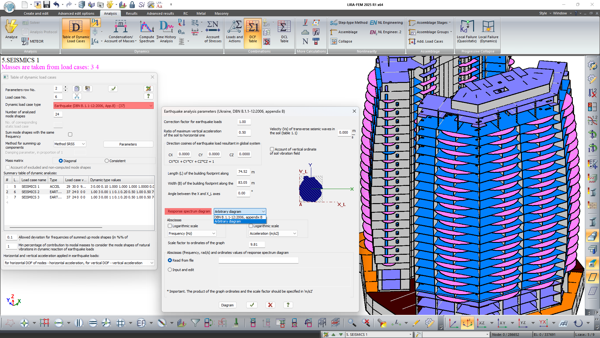
In the new version of dynamic module 37 (DBN V.1.1-12:2006, Appendix V), the option to use an arbitrary response spectrum graph in analyses has been introduced.
Dynamic module 37 allows one to account for the non-uniformity of the ground vibration field in analysis on earthquake loads. This model of earthquake analysis makes it possible to account for the spatial characteristics of structures with irregular layouts according to the propagation scheme of the seismic wave.
This model assumes that the plan of the structure is inscribed in a rectangular area of length L and width B. The propagating seismic wave moves along the long side, causing translational, rotational, and bending vibrations of the structure.
The effect of the seismic wave on the inertial seismic force magnitudes is taken into account using the ordinates of the ground vibration field fk1, fk2, fk3, which are introduced into the formula for the distribution coefficient ηki.
-
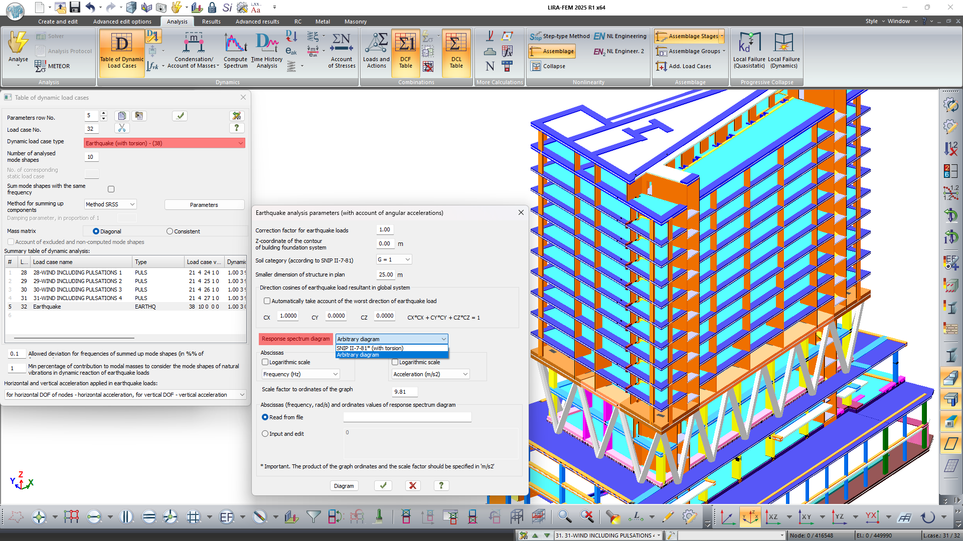
In module 38 (SNIP II-7-81 as amended on 01.01.2000 with torsion considerations), the option to use an arbitrary response spectrum graph in calculations has been added. The integrated model for analysis on earthquake load accounts for the movement of the ground mass under the structure as a single unit. This movement is determined by the vector of translational acceleration and the vector of angular acceleration of rotation.
It is assumed that these vectors are random both in time and space and are defined by the respective parameters. If the cosines for the translational impact vector are specified, then the direction of the angular acceleration vector is automatically calculated as orthogonal to the translational vector. The distribution coefficient in the calculation allows for obtaining inertial seismic forces not only for translational but also for torsional mode shapes.
-
The algorithm for the automatic selection of the step for geometrically nonlinear problems has been modernized.
-
An option has been added for the response spectrum graphs to set the output format of the abscissa values as oscillation frequency or period.
-
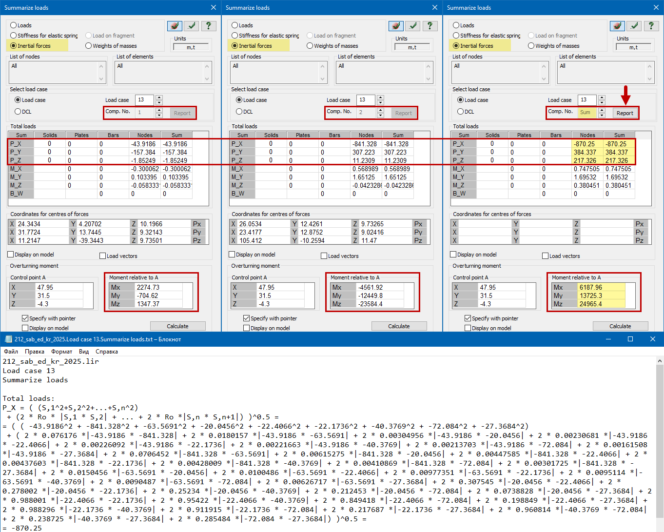
In the analysis results, on the "Summarize loads" menu, functionality has been added to determine the total shear forces and overturning moment from dynamic loads (earthquake and pulsation) for shear and overturning calculations. The summation is performed using the same method (SSRS, CQC, 10%) selected in the dynamic action parameters. A detailed report can be generated based on the summation results for verification and/or documentation purposes.
Analysis options Ц Enhancements
In addition to the existing combinations generated by DCF and DCL, a new algorithm is implemented to determine combinations of individual load cases that may be significant (the most dangerous) for each checked element and each node of the design model. The new method combines all the advantages of the previous methods and adds new features: work with a large number of combinations (more than 1000 combinations), user-defined settings for types and subtypes of load cases, user-defined combination formulas, formula representation of logical relationships, matrix representation of mutually exclusive load cases and much more.
A new type of uniformly distributed load on bars and plates is implemented in problems with time history analysis. The following load variation diagrams are available: piecewise linear load with arbitrary or uniform step, as well as sinusoidal load.
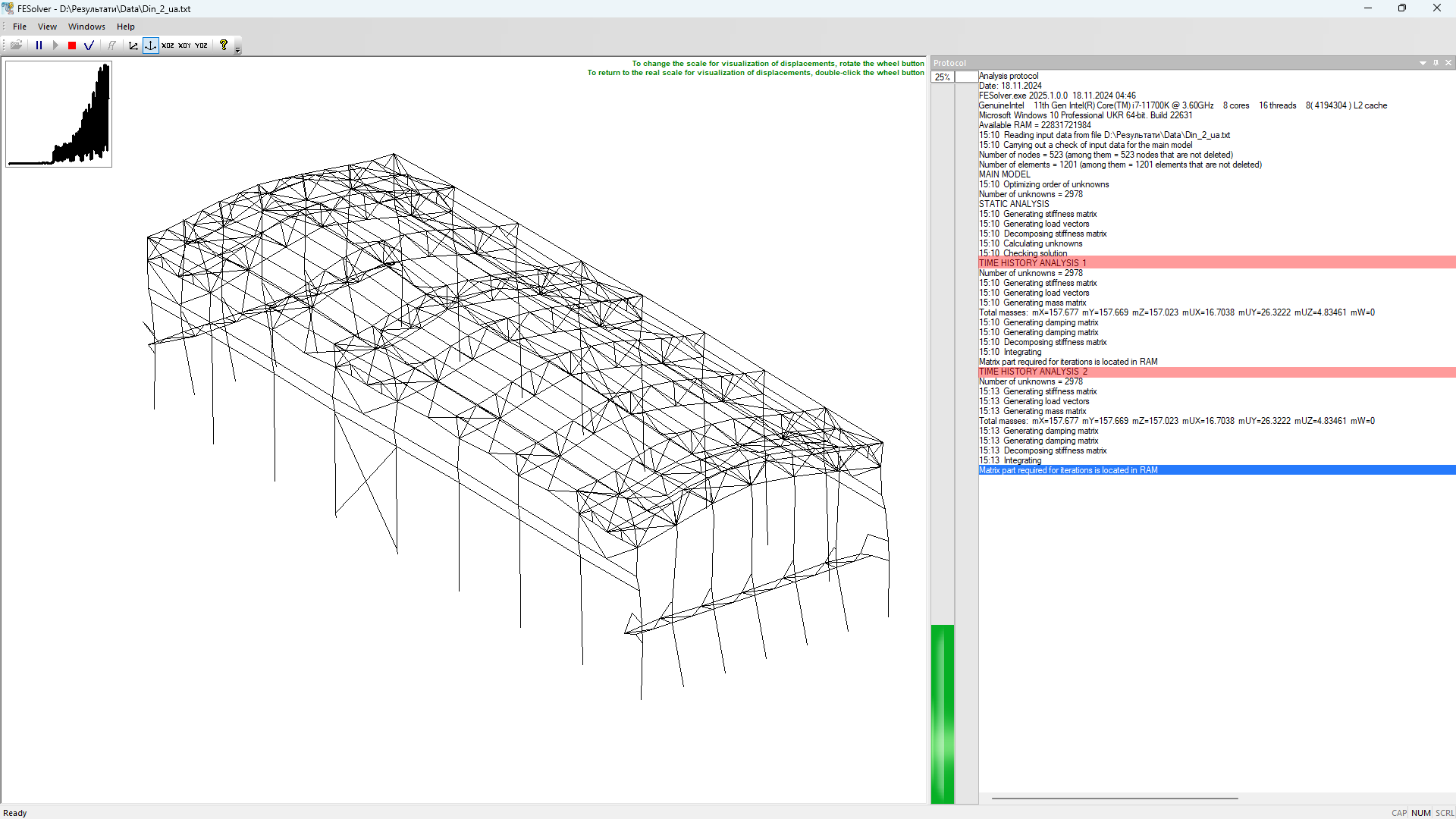
New option to define multiple time history analyses with different parameters within a single design model.
New type of stiffness for plates ' user-defined elasticity matrix.
For the spectral method of earthquake analysis, the damping ratio of mode shapes is calculated through the damping matrix.
New option to check the value of min percentage of contribution to modal masses to consider the mode shapes of natural vibrations in dynamic reaction of earthquake loads.
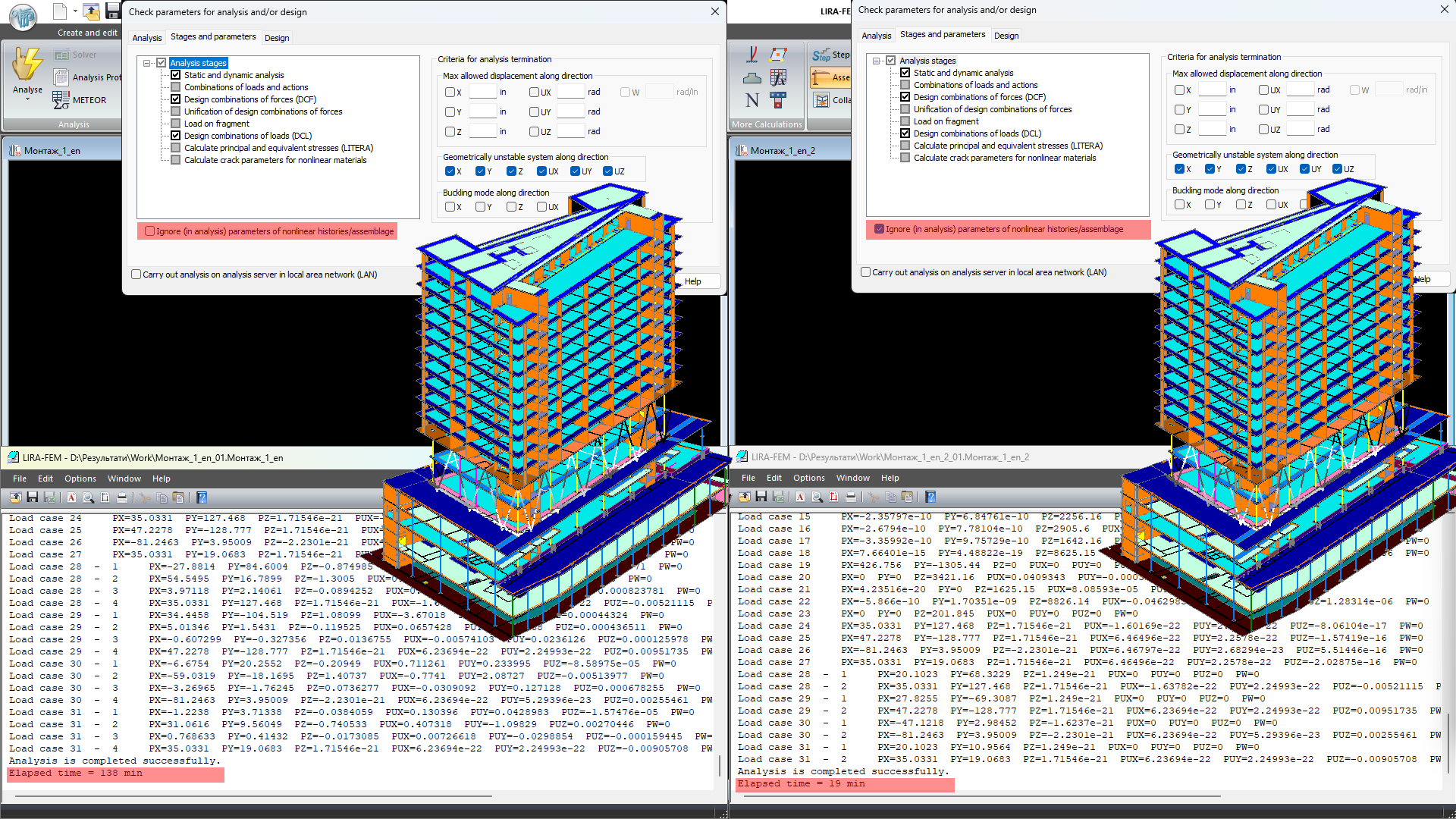
When you check parameters and analyse the problem, there is a new option that enables you to ignore in analysis the parameters of step-type process for solution of nonlinear problems, problems of assemblage-disassemblage of a structure, problems with progressive collapse, problems of engineering nonlinearity 1 and 2. This option can be used for preliminary high-speed calculations; in this case the data on nonlinear history/assemblage should not be deleted. When the "Ignore (in analysis) parameters of nonlinear histories/assemblage" option is selected, the analysis is performed on the specified load cases as analysis of a standard problem.
The Check parameter for analysis and/or design dialog box is modified; the analysis by solver of previous versions is excluded
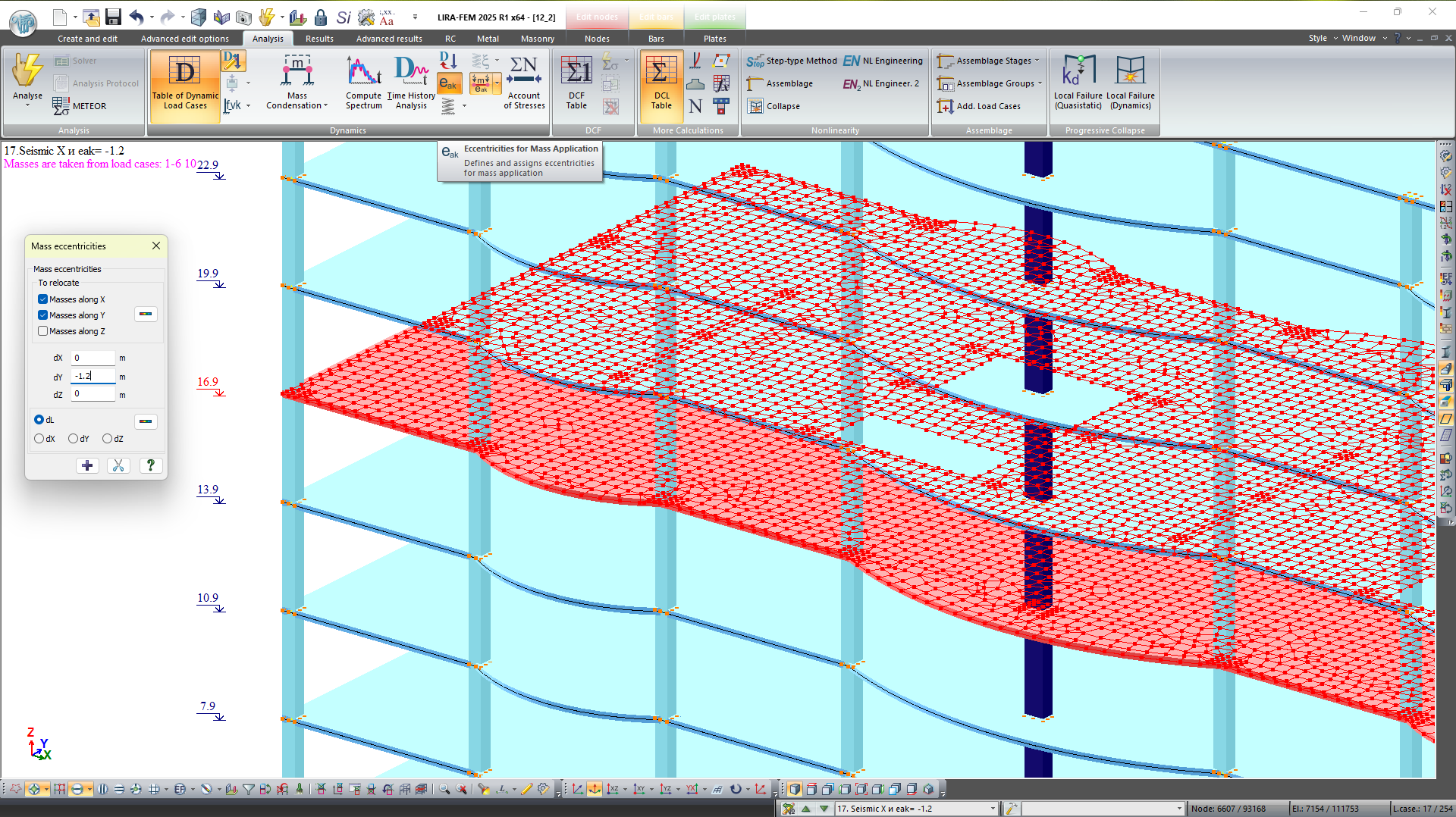
For dynamic analyses in case of displacement of nodal masses, it is possible to define the masses of which directions should be moved.
The option to consider the Rayleigh coefficients for earthquake analysis by the method of decomposition by mode shapes of natural vibrations.
To calculate the subgrade moduli C1/C2 and to calculate the pile stiffness, there is an option to exclude from iterations the loads that are not considered in clarifying the active pressure on the soil Pz.
New option to determine forces in bar analogues (BA) for load cases defined "by formula" (load cases created as a combination of analysis results of an arbitrary set of other load cases)
An algorithm is implemented to recalculate the original accelerogram to a specified height elevation different from the test measurement level.
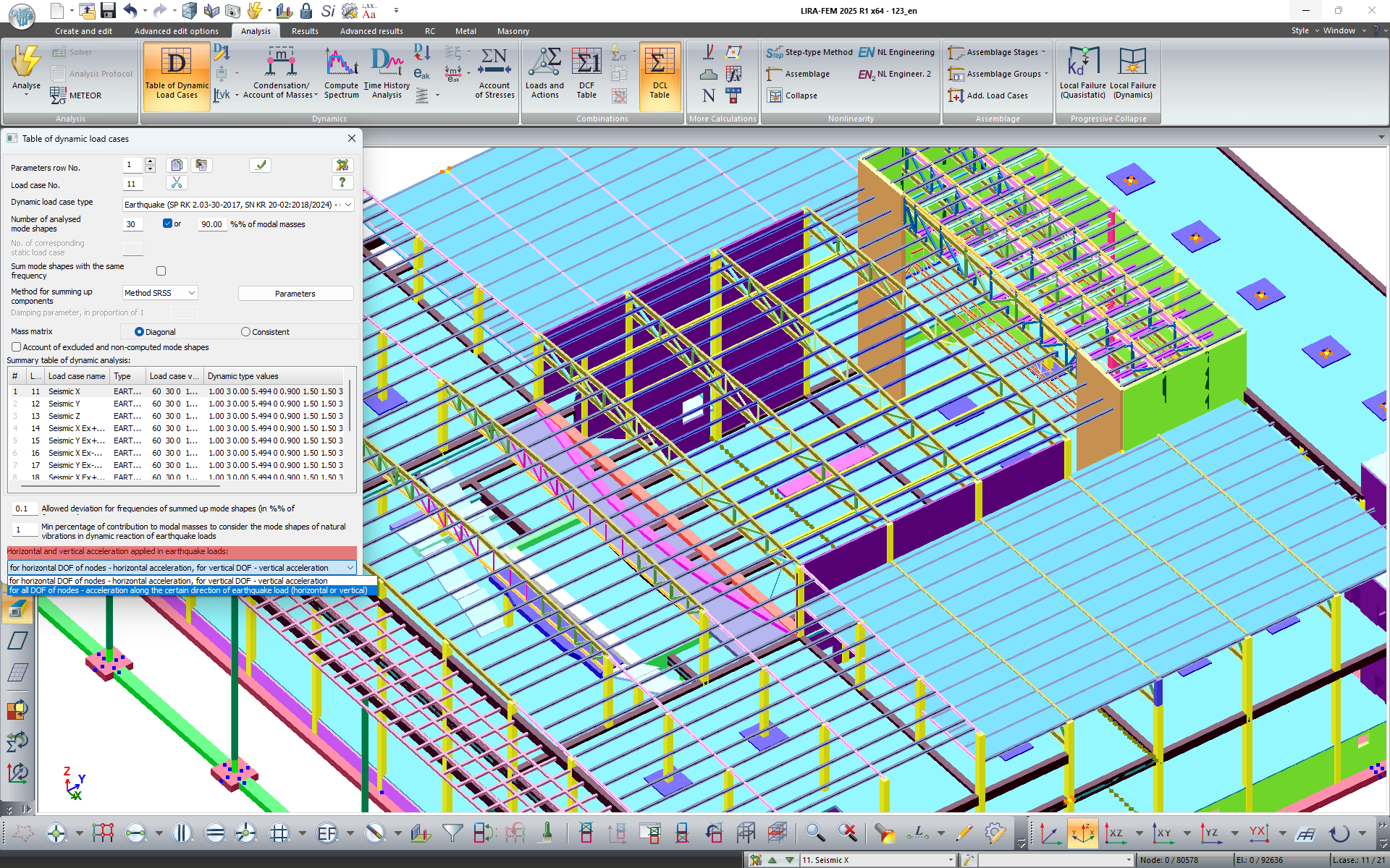
An optional way of applying horizontal and vertical accelerations in earthquake analyses has been implemented. Many seismic building codes have a separation between horizontal and vertical acceleration. Previously, in the same component of the same earthquake load, horizontal acceleration was applied to horizontal degrees of freedom (DOF) of nodes and vertical acceleration was applied to vertical degrees of freedom. Now optionally, if it is a horizontal load, then horizontal acceleration is applied to all DOF of the nodes, and if it is a vertical load, then vertical acceleration is applied.


