

SOIL
Modeling of elastic foundation. Calculation of elastic foundation coefficients. Determination of soil deformations and building settlement. Calculation of pile stiffness.
Based on the data of engineering-geological surveys of the construction site (borehole locations and characteristics), a three-dimensional soil model is built. According to this model, the values of subgrade reaction coefficients C1, C2 are determined over the entire area of the slab, depending on the loads on the foundation slab and the loads from adjacent buildings, and the depth of the compressible stratum and the settlement are also calculated.
The settlement and the depth of the compressible stratum are calculated using the linearly elastic half-space scheme in accordance with the following normative documents:
- DBN V.2.1-10:2009. Bases and foundations of buildings and structures. Basic design provisions
- SNiP 2.02.01-83*. Bases of buildings and structures
- EN 1997-1:2004: Eurocode 7: Geotechnical design - Part 1: General rules
- SP RK 5.01-102-2013. Bases of buildings and structures
- SP 22.13330.2011/2016. Bases of buildings and structures
- SP 50-101-2004. Design and construction of bases and foundations of buildings and structures
For the standards DBN V.2.1-10:2009, SP 22.13330.2011/2016, SP RK 5.01-102-2013, the analysis of the structure's foundation accounting for soil consolidation and creep is performed.
The SOIL system also implements the calculation of foundation bearing strength according to EN 1997-1:2004 Eurocode 7. These standards describe three design approaches for the foundation. Each of them reflects a specific way of combining sets of individual coefficients to obtain design values for the action of load and foundation resistance.
The latest news on the development of the SOIL system is available via the link.
Initial Data
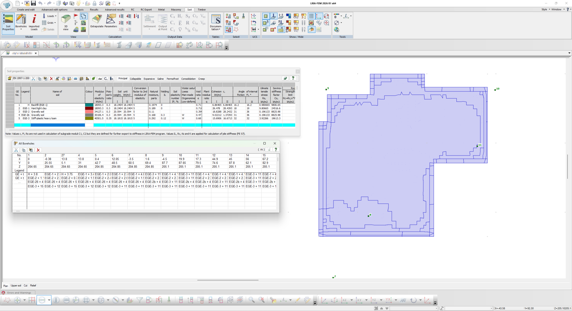
To model the soil foundation under a structure, it is necessary to specify a set of initial data, such as the number and names of soil layers (engineering-geological elements), the mechanical and physical characteristics of each layer, and the number and location of boreholes.
After that, it becomes possible to perform extrapolation and obtain a 3D model and a soil cross-section. The cross-section can be drawn between arbitrary points.
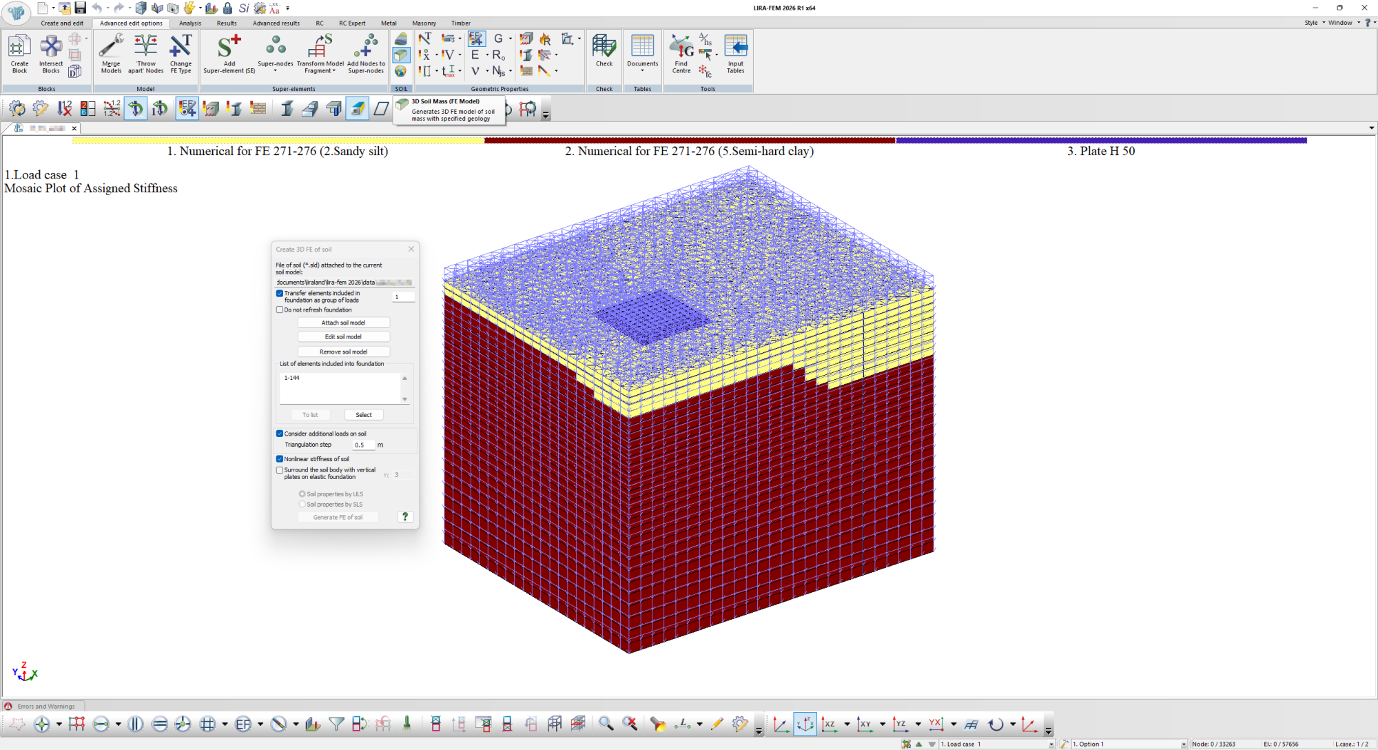
Based on the cross-section and the 3D soil model, it is possible to generate a finite element model of a plane or solid soil mass, respectively, with automatic determination of the stiffness of each finite element depending on its location within the various layers.
This model can be used to calculate the system: superstructure, foundation structures, and soil mass.
Elastic Foundation Coefficients (C1, C2)
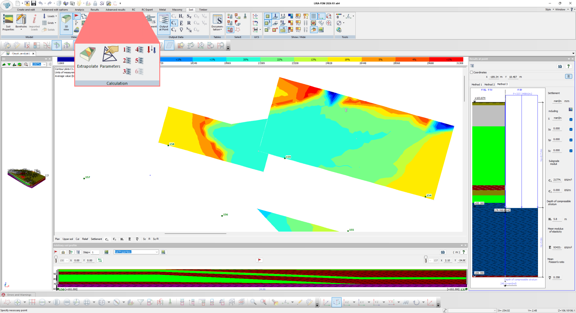
The elastic foundation coefficients C1 and C2 can be assigned to bars and plates manually, or determined automatically using the following methods:
- Method 1. Calculation for the Pasternak model
- Method 2. Calculation for the Winkler-Fuss model
- Method 3. Modified calculation for the Pasternak model
- Method 4. Modified calculation of the elastic foundation using Savinov's formula
- Method 5. Calculation of the elastic foundation using Formula 4 of SNiP 2.02.05-87 "Foundations of machines with dynamic loads"
- Method 6. Calculation of the elastic foundation accounting for the effect of dynamic waves on the elastic properties of the soil
More details on the methods for calculating the elastic foundation coefficients can be found below:
The value of the elastic foundation coefficient C1 at the design point with coordinates (x, y) is determined by the formula:
|
|
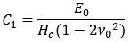
The value of the elastic foundation coefficient C1 at the design point with coordinates (x, y) is determined by the formula:
|
|

where q is the value of the uniformly distributed load at the design point with coordinates (x, y).
The value of the elastic foundation coefficient C1 at the design point with coordinates (x, y) is determined, as in Method 1, by the formula:
|
|
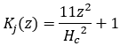
with the difference that when determining the average deformation modulus E0, a correction coefficient Kj is taken into account, and the additional vertical stress is distributed uniformly with depth:
|
|

The same coefficient is also introduced when determining the settlement:
|
|
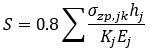
It is assumed that the coefficient K varies from 1 to 12 according to a quadratic parabola law within the compressible stratum Hc
|
|
Method 3 was proposed to eliminate the shortcomings identified when evaluating the calculation results of the first two methods.
In Method 1, this is the inability to account for the increase of the deformation modulus with depth, which leads to overestimated settlement values and, consequently, to underestimated values of the elastic foundation coefficient C1.
In Method 2, this is the presence of a sharp jump in the values of the elastic foundation coefficient C1 at locations of abrupt changes in the applied load values. Note that this shortcoming of Method 2 persists even when using a deformation modulus that increases with depth.
Evaluation of the calculation results for Method 3 showed that these results are close to the calculation results obtained using the linearly deformable layer scheme.
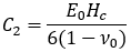
For Methods 1 and 3, the value of the elastic foundation coefficient C2 at the design point with coordinates (x, y) is determined by the formula
|
|
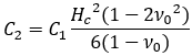
For Method 1, this formula can be written as
|
|
Savinov's formula makes it possible to determine the elastic foundation coefficient C1 under dynamic effects on the foundation, and looks as follows:
|
|
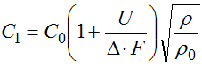 , where
C0 – soil elasticity constant, tf/m3;
U – foundation perimeter, m;
F – foundation area, m2;
p – average pressure under the footing,
p0 – pressure on the test plate, equal to 2 tf/m2;
Δ – elastic constant of the foundation, taken equal to 1 m-1.
Formula 4 makes it possible to determine the coefficient of elastic uniform compression Cz (C1z) under dynamic effects on the foundation, and looks as follows:
|
|
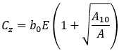 , where
b0 – coefficient, m-1, which is taken equal to 1 for sandy soils, 1.2 for sandy loams and loams, and 1.5 for clays and coarse clastic soils;
E – deformation modulus of the soil under the foundation footing, kPa (tf/m2), determined in accordance with the requirements of SNiP 2.02.01.83;
А10 = 10 m2;
А – area of the foundation footing, m2.
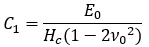
This method is based on the Pasternak model, according to which the elastic foundation coefficient C1 is calculated by the formula:
|
|
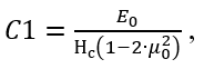
where Нс is the depth of the compressible zone, μ0 is the average value of Poisson's ratio, E0 is the average value of the soil deformation modulus.
When calculating for dynamic oscillations, three types of soil particle motion are considered: translational motion along the z-axis and two types of oscillations (about the x-axis and the y-axis). Therefore, instead of a single value of the elastic foundation coefficient С1, three values are considered (Cz, C1xx, C1yy), each of which reflects the behavior of the elastic foundation in the specified direction resulting from the corresponding type of particle motion. This is therefore written as follows:
|
|
|
|
|
|
|
|
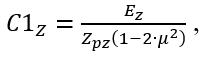
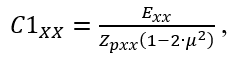
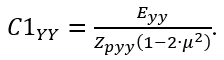
Where Zpz is the thickness of soil required for analyzing the foundation behavior under translational motion of soil particles, and Zpxx, Zpyy are the thicknesses of soil required for analyzing the foundation behavior under oscillatory motion.
In the calculation for Method 6, Poisson's ratio μ is determined from the ratio between the propagation velocities of transverse and longitudinal dynamic waves and is calculated using the formulas:
|
|

Where Vsoz, Vsoxx, Vsoyy are the propagation velocities of transverse waves, and Vpoz, Vpoxx, Vpoyy are the propagation velocities of longitudinal waves.
The wave velocities Vsoz, Vsoxx, Vsoyy, Vpoz, Vpoxx, Vpoyy used to calculate the elastic foundation coefficients are determined as the load-weighted arithmetic means of the averaged wave velocities at each point. The values of the averaged wave velocities at each load point are calculated using the formulas:
|
|
|
|
|


Where Vsi, Vpi are the experimental values of the propagation velocities of transverse and longitudinal waves in an elementary soil layer, specified by the user.
When calculating the elastic foundation coefficients C1Z, C1XX, C1YY, the values of effective elastic moduli are used, which are calculated using the formulas:
|
|
|
|
|
|
|
|



Where Gz, Gxx, Gyy are the values of the effective shear moduli, determined by the formulas:
|
|
|
|
|
|
|
|
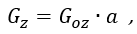
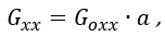
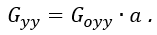
Where a is a coefficient taken from Table D.2 of document [1]. This coefficient depends on the design acceleration of the foundation (as a fraction of g), which is taken from the initial data.
|
|
|
|
|
|
|
|
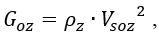

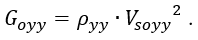
Where ρz, ρxx, ρyy are the average specific masses of the soil, determined in the same way as the propagation velocities of transverse and longitudinal waves used in calculating Poisson's ratio. That is, the values ρz, ρxx, ρyy are calculated as the load-weighted arithmetic means of the averaged unit weight values ρz, ρxx, ρyy at each point, calculated using the formulas:
|
|

Where ρi is the unit weight value of the i-th soil layer, taken from the "Soil Characteristics" table.
[1] Regulatory and technical guide SP RK EN 1998-1:2004/2012 "Design of seismic-resistant buildings. Part: design of civil buildings. General requirements".
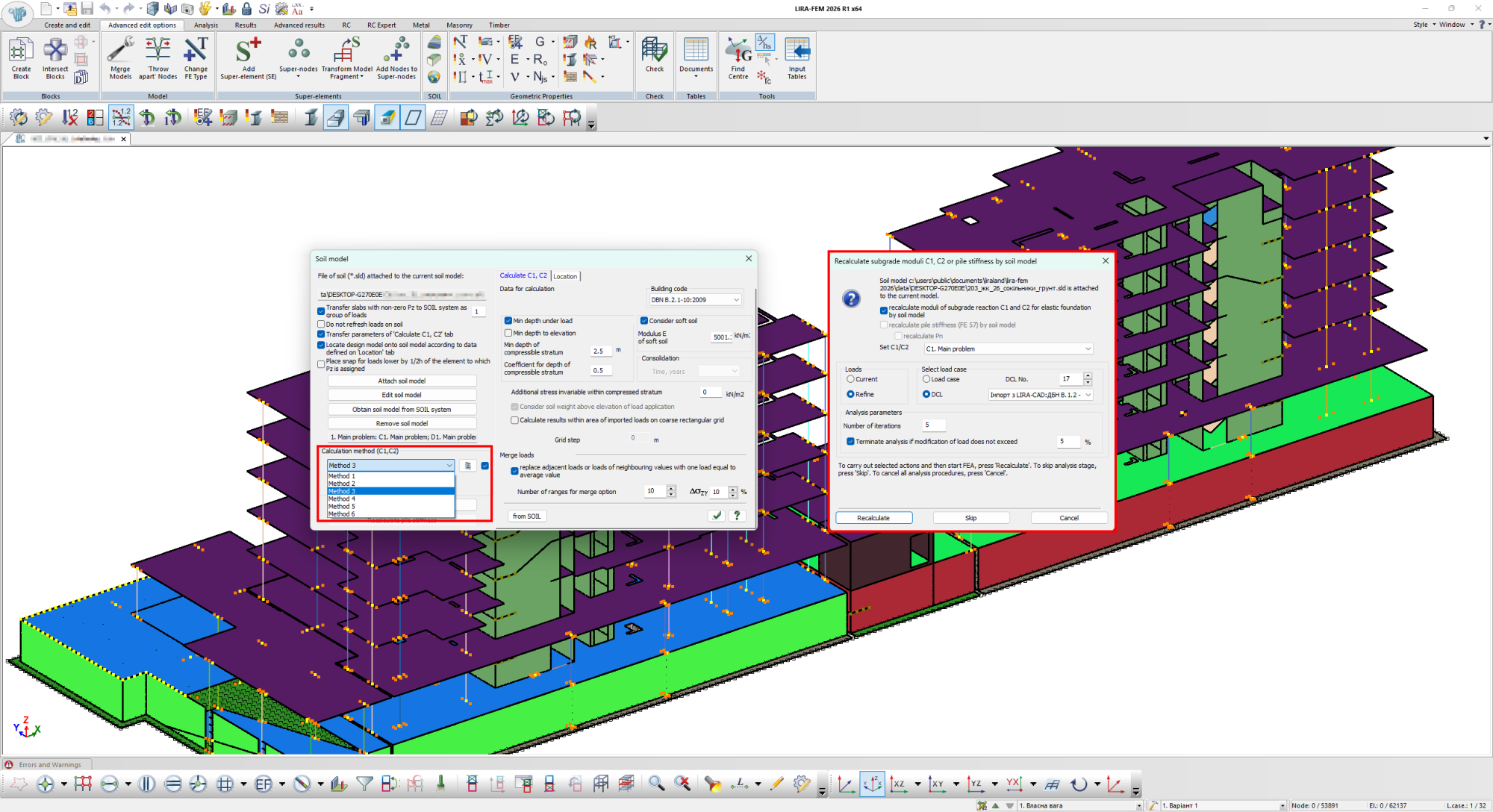
The calculation of the elastic foundation (subgrade reaction) coefficients is performed in the local SOIL system, as well as during the overall calculation of the model in LIRA-FEM. In the second case, it is possible to perform a recalculation of the coefficients C1 and C2.
The recalculation is performed by refining the initial soil resistance Pz, which depends on the coefficients C1, C2, which in turn depend on the soil resistance Pz. In other words, the process of calculating the subgrade reaction coefficients is iterative. The user can specify the number of iterations or the % of convergence with the previous result.
Horizontal and Rotational Stiffness of the Elastic Foundation
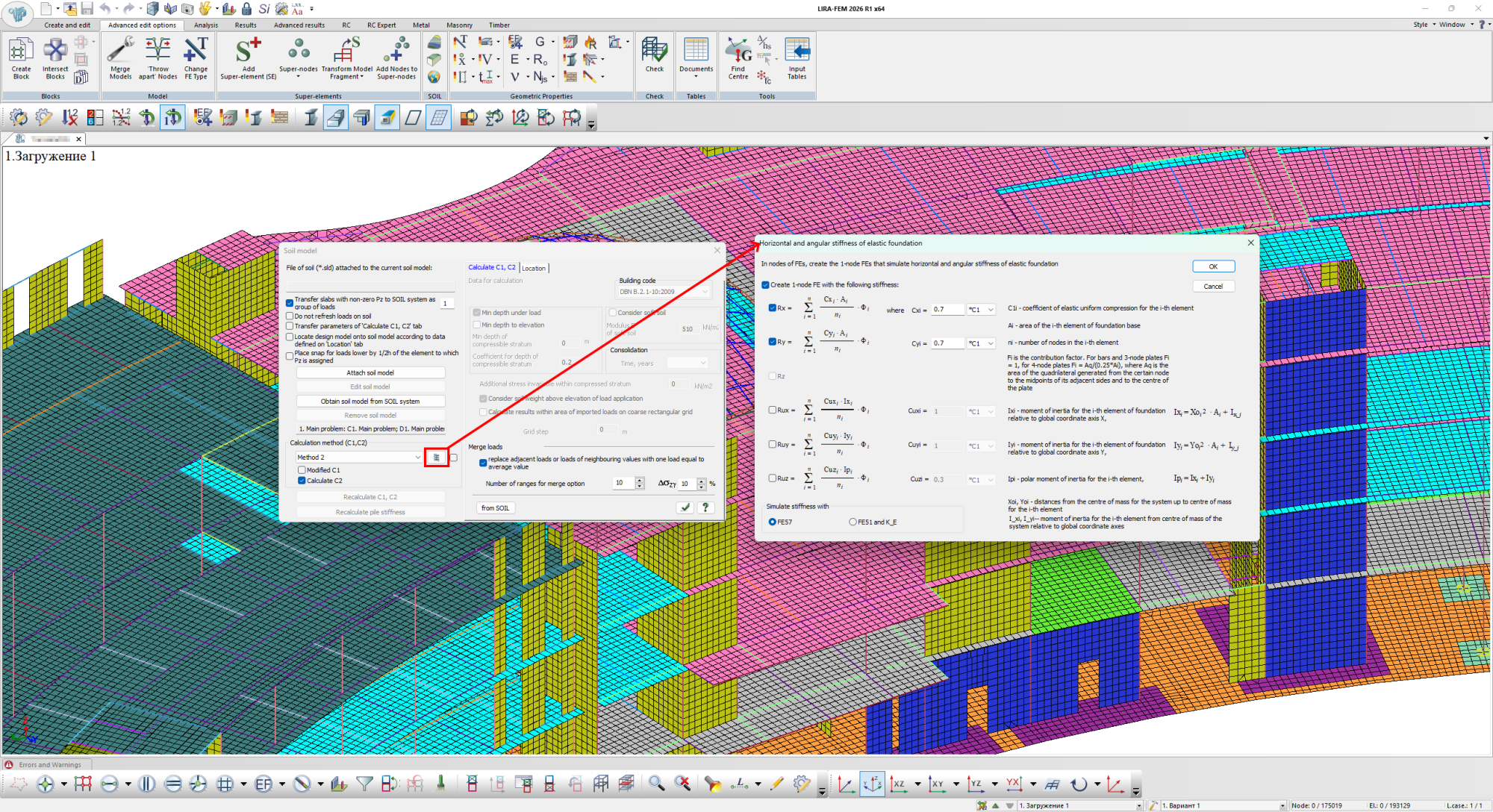
LIRA-FEM makes it possible to automatically calculate and model the horizontal and rotational stiffness of the foundation.
For each of the five directions of horizontal and rotational stiffness (Rx, Ry, Rux, Ruy, Ruz), the user chooses the approach: to let the program calculate it as a fraction of the coefficient Cz, or to specify an exact numerical value manually.
The program automatically models the horizontal stiffness using either a simple FE57 element - for quick calculations, or a more detailed group of FE51 elements - with a separate coefficient applied to the elastic modulus for each direction, which can be checked and viewed separately.
Accounting for Problem Soils
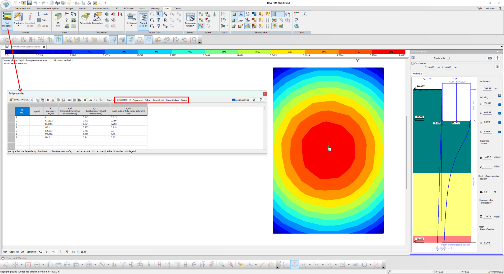
LIRA-FEM (the SOIL system) implements the calculation of foundations for structures built on certain problem soils, namely: collapsible, swelling, saline, organic, and man-made (fill) soils.
The calculation is performed in accordance with the following standards:
- DBN V.2.1-10:2009 "Bases and foundations of structures"
- SP RK 5.01-102-2013 "Bases of buildings and structures"
- SP 22.13330.2016 "SNiP 2.02.01-83* Bases of buildings and structures"
Deformations caused by problem soils are always taken into account only within the compressible stratum.
Calculation of Pile Stiffness
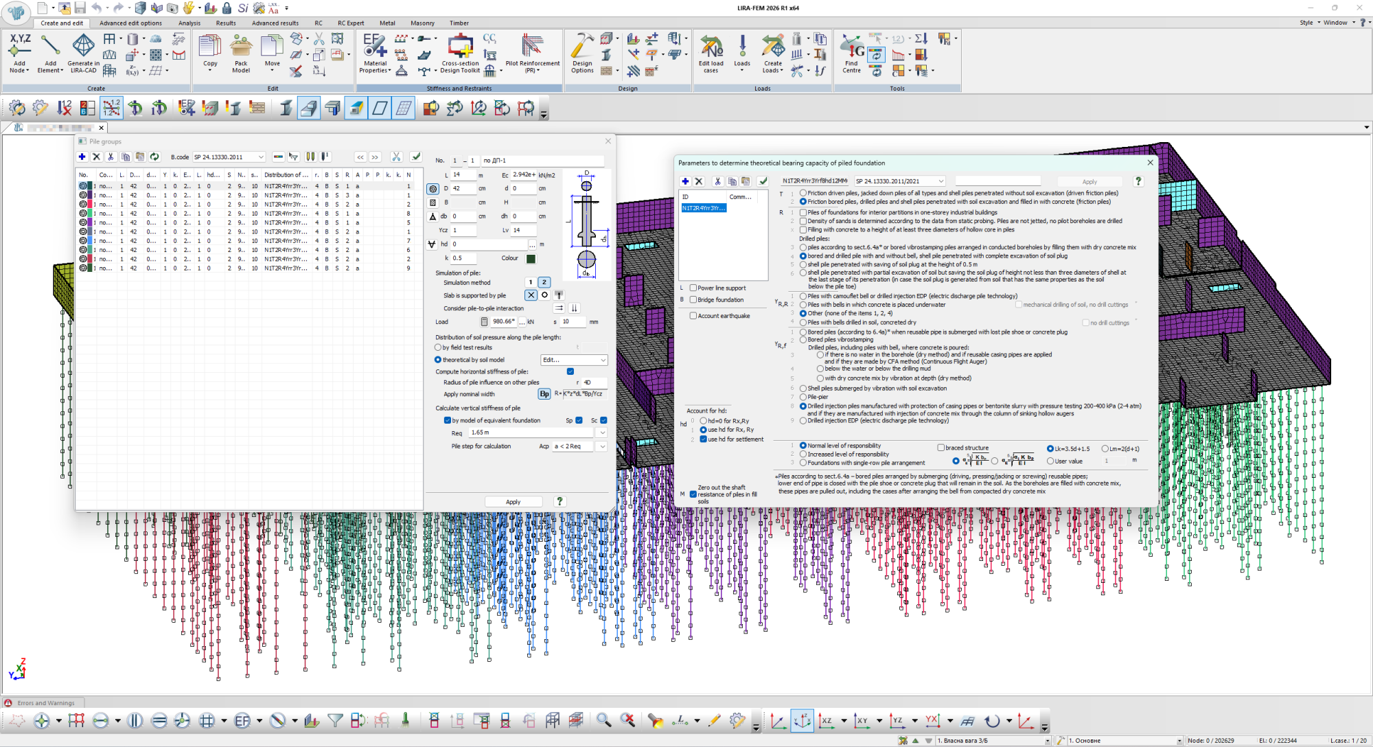
LIRA-FEM makes it possible to automatically calculate the vertical and horizontal stiffness of piles.
The program allows piles to be modeled using single-node FE 56, 57 elements, as well as bar elements. Stiffness can be specified either based on survey results or calculated automatically.
The program automatically calculates the stiffness of piles under identical soil conditions, or the stiffness of a pile foundation.
The calculation of pile stiffness is performed according to the standards DBN V.2.1-10:2009, SP RK 5.01-102-2013, and SP 24.13330.2011.
Evaluate the software
If you have any doubt, download the Demo version and evaluate the program or contact our Support Team for more details.