VERSION HISTORY
LIRA-FEM
- Components of BIM technology
- Generating and modifying the model
- Generating and modifying the design model
- Analysis options
- Tools for evaluation of object properties and analysis results
- Analysis & design of reinforced concrete (RC) structures
- RC Expert
- Analysis & design of steel structures
- Soil
- Cross-Section Design Toolkit
- Documentation improvements
LIRA-FEM 2025 R2
Documentation improvements
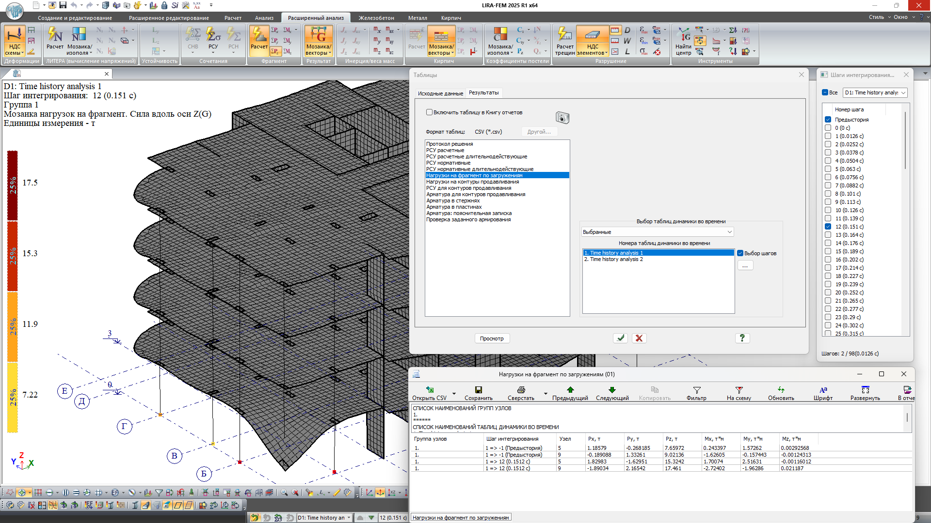
- In problems with time history analysis, the option to document analysis results in tabular format for selected integration steps has been implemented.
- The option to use an extreme force filter has been added for cases when a structural element consists of a single finite element.
- On the Errors and Warnings tab of the results tables for analysis of steel structures, a separate column has been added listing the element numbers.
- In LIRA-FEM 2025, support for Interactive Tables, the BRIDGE system tables, and the Report (old format) has been discontinued. In the current version, these commands have been removed from the ribbon interface, although they can still be launched via the WINDOW menu.
Cross-Section Design Toolkit
- Added the option to assign linear heat‐technical characteristics to materials, with their subsequent export to the 15th model type.
- Calculation of the sectional moment of resistance of the cross-section has been added to the characteristics table.
Analysis & design of steel structures
- To control the input data and results of the analysis of steel sections in accordance with the DBN V.2.6-:198:2014 standards, mosaic plots of cross-sectional classes have been implemented. The input data and analysis results tables have been expanded.
- A filter of steel tables by the formed groups has been added. After its application, only the steel tables from the selected groups will be displayed in the parameter assignment lists for metal sections or in the list of the Editable Steel Table system.
Analysis & design of reinforced concrete (RC) structures
- For the DBN V.2.6-98:2009 standards, the option to output the safety factor for the specified reinforcement as an envelope result for each check has been added.
- For the DBN V.2.6-98:2009 standards, the option to determine the strength safety factor for precise reinforcement pattern in PR types has been added.
Soil
-
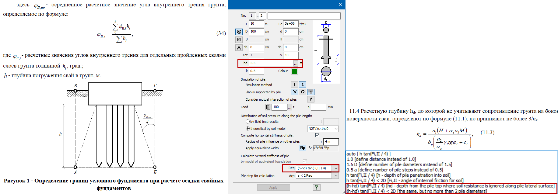
New options for generating Equivalent Foundations for piles have been implemented: when calculating Req using the formula h*tg(θII/4), where h is the depth of pile penetration into the soil, the effect of the depth hd—at which the load-bearing capacity fi of the pile’s lateral surface is not taken into account—has been added. Moreover, if the parameter “h-hd” results in a value of Req less than 0.5D (half the pile’s diameter), then Req is set to 0.5D.
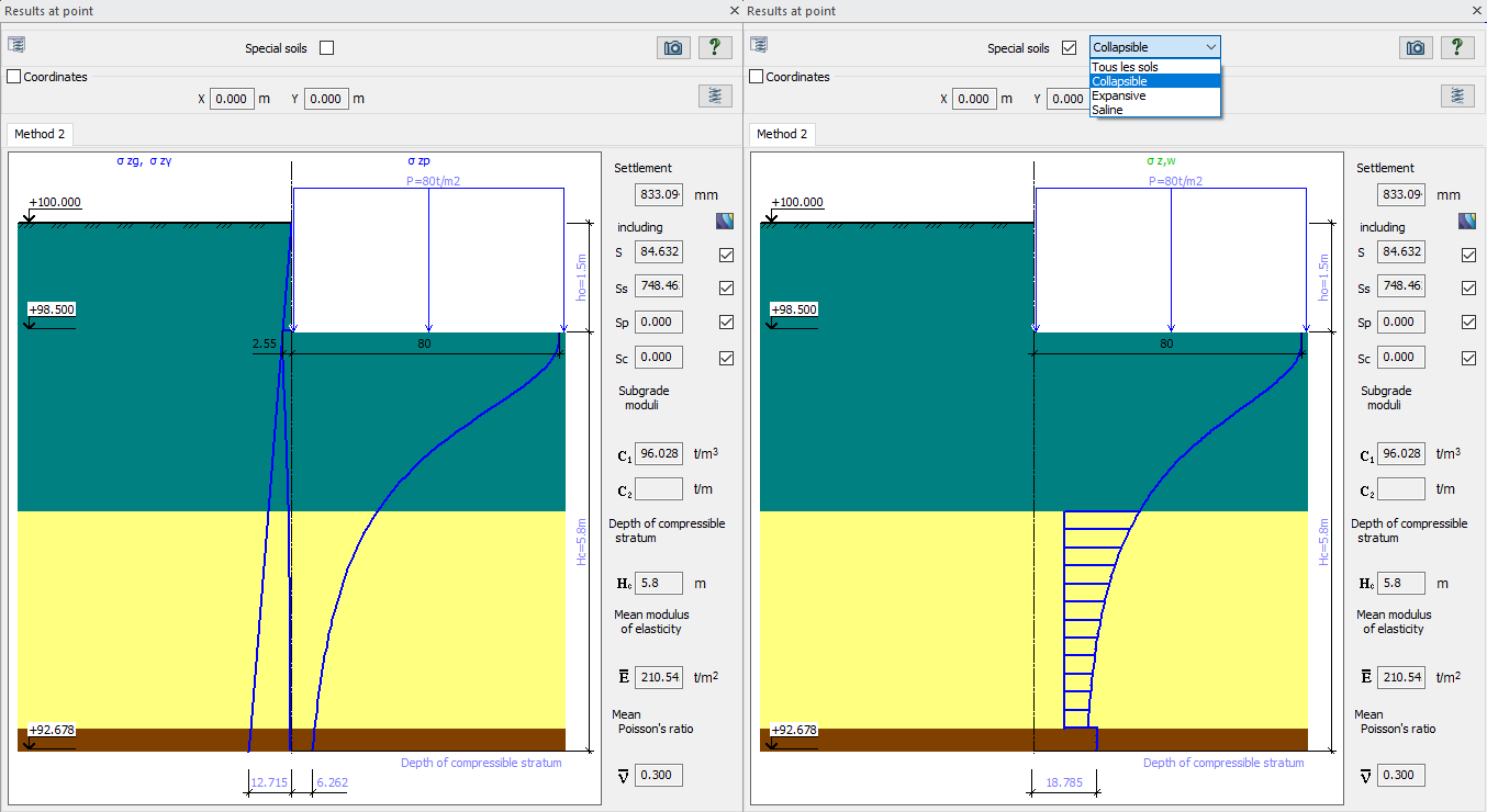
- In the "Results at a Point" dialog box, an option has been added to display calculation results for specific soils. This visualization allows for examining calculation details, serving as a partial trace of the computation. For example, for settlement soils, a hatched area of the full stress diagram Sz is shown, which contributed to the settlement calculation due to consolidation – clearly showing the initial settlement pressure and the extent to which the total stress Sz exceeds the initial settlement pressure layer by layer. Keep in mind that the total stress Sz includes the weight of the settlement soil with the buoyant effect of water taken into account, although in the original calculation without settlement the soil was treated as undrained (waterlogged). Thus, on the new diagram for calculating the specific soil under the foundation of the settlement layer, a jump in stresses is visible that is absent in the calculation without settlement.
- In the scale settings, an option has been added to display percentages in the scale ranges – indicating what fraction of the original data points and computation results fall within the given range.
- In the legend (textual accompaniment) for the calculation results (settlement and subgrade coefficients), the average value calculated from all load contours is now displayed.
Enhancements to Analysis Capabilities
-
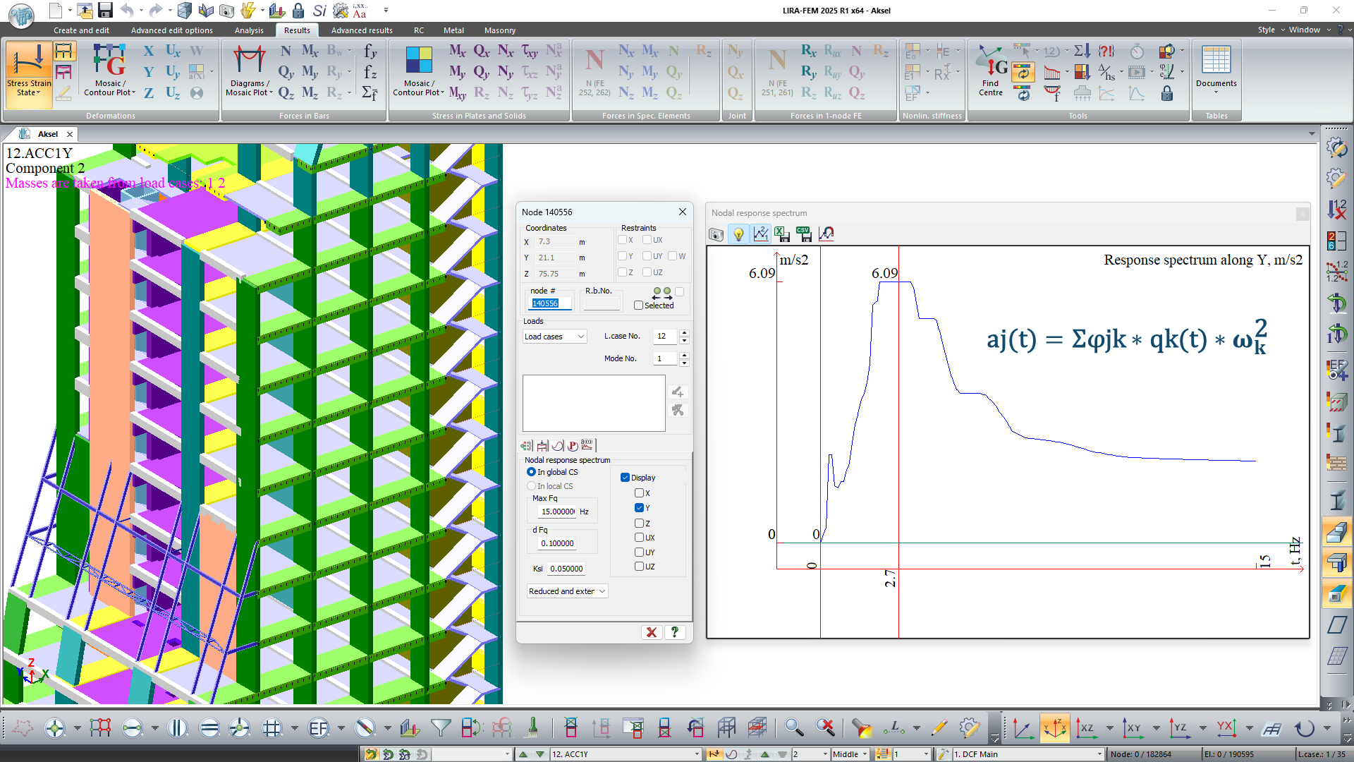
When generating response spectrum graphs using module 27, the approach for determining the final accelerations—taking into account all mode shapes on which the spectrum is based—has been adjusted.
Now the spectrum is generated based on the graph of pseudo-acceleration changes (floor accelerogram), where the acceleration at each moment is determined as follows:
aj(t) = ΣΔjk * qk(t) * ωk²,
where aj(t) is the acceleration of the j-th degree of freedom at time t,
Δjk is the ordinate of the j-th degree of freedom for the k-th mode,
qk(t) is the generalized coordinate for the k-th vibration mode at time t,
ωk is the circular frequency for the k-th vibration mode.This approach produces results analogous to those obtained by direct integration of the equations of motion in geometric coordinates.
-
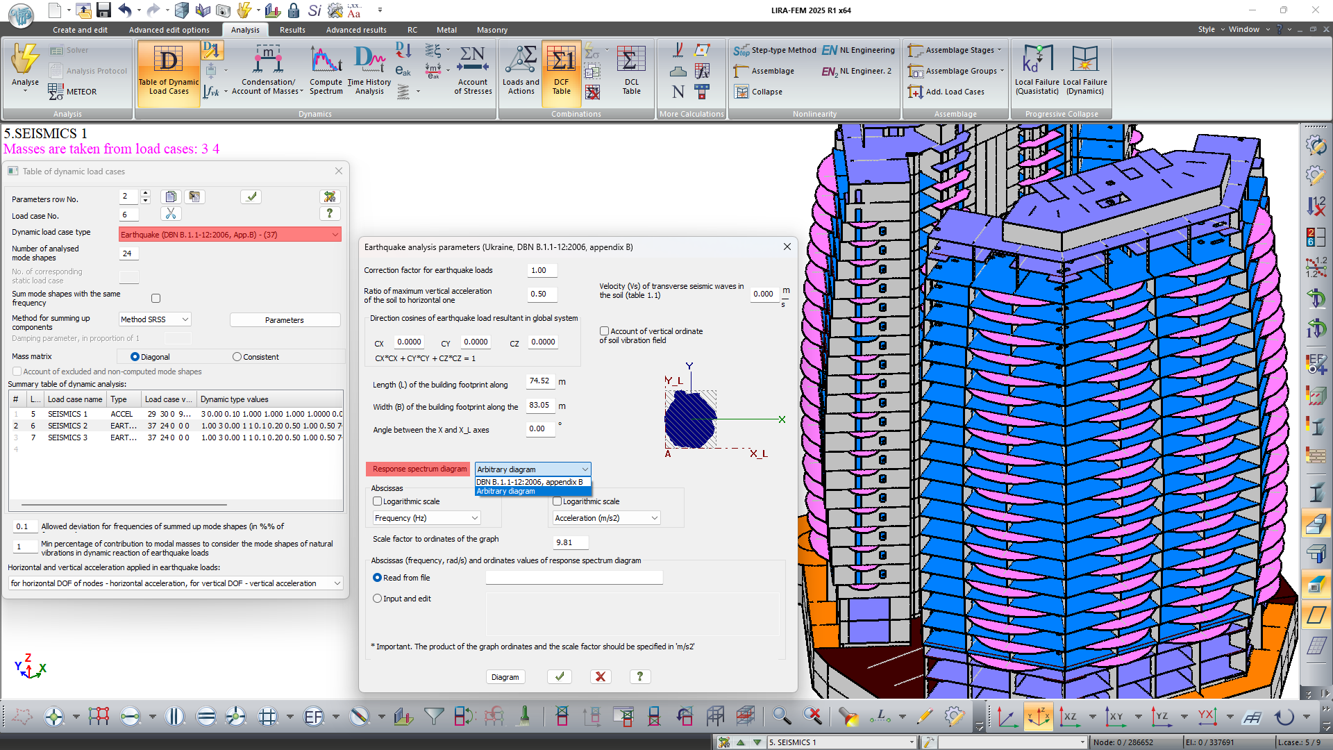
In the new version of dynamic module 37 (DBN V.1.1-12:2006, Appendix V), the option to use an arbitrary response spectrum graph in analyses has been introduced.
Dynamic module 37 allows one to account for the non-uniformity of the ground vibration field in analysis on earthquake loads. This model of earthquake analysis makes it possible to account for the spatial characteristics of structures with irregular layouts according to the propagation scheme of the seismic wave.
This model assumes that the plan of the structure is inscribed in a rectangular area of length L and width B. The propagating seismic wave moves along the long side, causing translational, rotational, and bending vibrations of the structure.
The effect of the seismic wave on the inertial seismic force magnitudes is taken into account using the ordinates of the ground vibration field fk1, fk2, fk3, which are introduced into the formula for the distribution coefficient ηki.
-
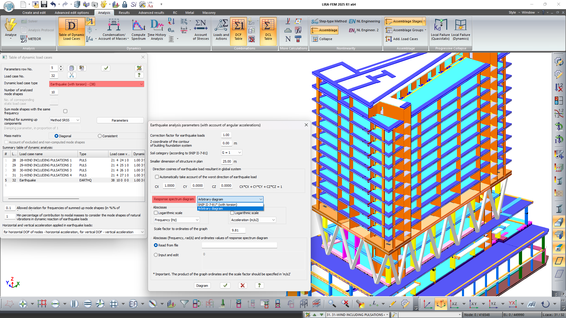
In module 38 (SNIP II-7-81 as amended on 01.01.2000 with torsion considerations), the option to use an arbitrary response spectrum graph in calculations has been added. The integrated model for analysis on earthquake load accounts for the movement of the ground mass under the structure as a single unit. This movement is determined by the vector of translational acceleration and the vector of angular acceleration of rotation.
It is assumed that these vectors are random both in time and space and are defined by the respective parameters. If the cosines for the translational impact vector are specified, then the direction of the angular acceleration vector is automatically calculated as orthogonal to the translational vector. The distribution coefficient in the calculation allows for obtaining inertial seismic forces not only for translational but also for torsional mode shapes.
-
The algorithm for the automatic selection of the step for geometrically nonlinear problems has been modernized.
-
An option has been added for the response spectrum graphs to set the output format of the abscissa values as oscillation frequency or period.
-
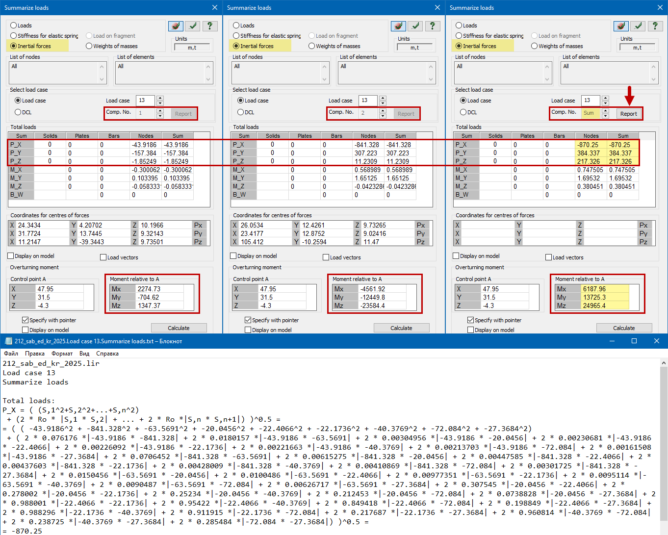
In the analysis results, on the "Summarize loads" menu, functionality has been added to determine the total shear forces and overturning moment from dynamic loads (earthquake and pulsation) for shear and overturning calculations. The summation is performed using the same method (SSRS, CQC, 10%) selected in the dynamic action parameters. A detailed report can be generated based on the summation results for verification and/or documentation purposes.
Tools for evaluation of object properties and analysis results
- New mosaic plots have been implemented:
- Mosaic plots of effective lengths of reinforced concrete bars and plates (walls) relative to the local axes Z1 and Y1;
- Mosaic plots of cross-sectional classes for checking and selecting transverse steel sections for DBN V.2.6-198:2014 "Steel Structures".
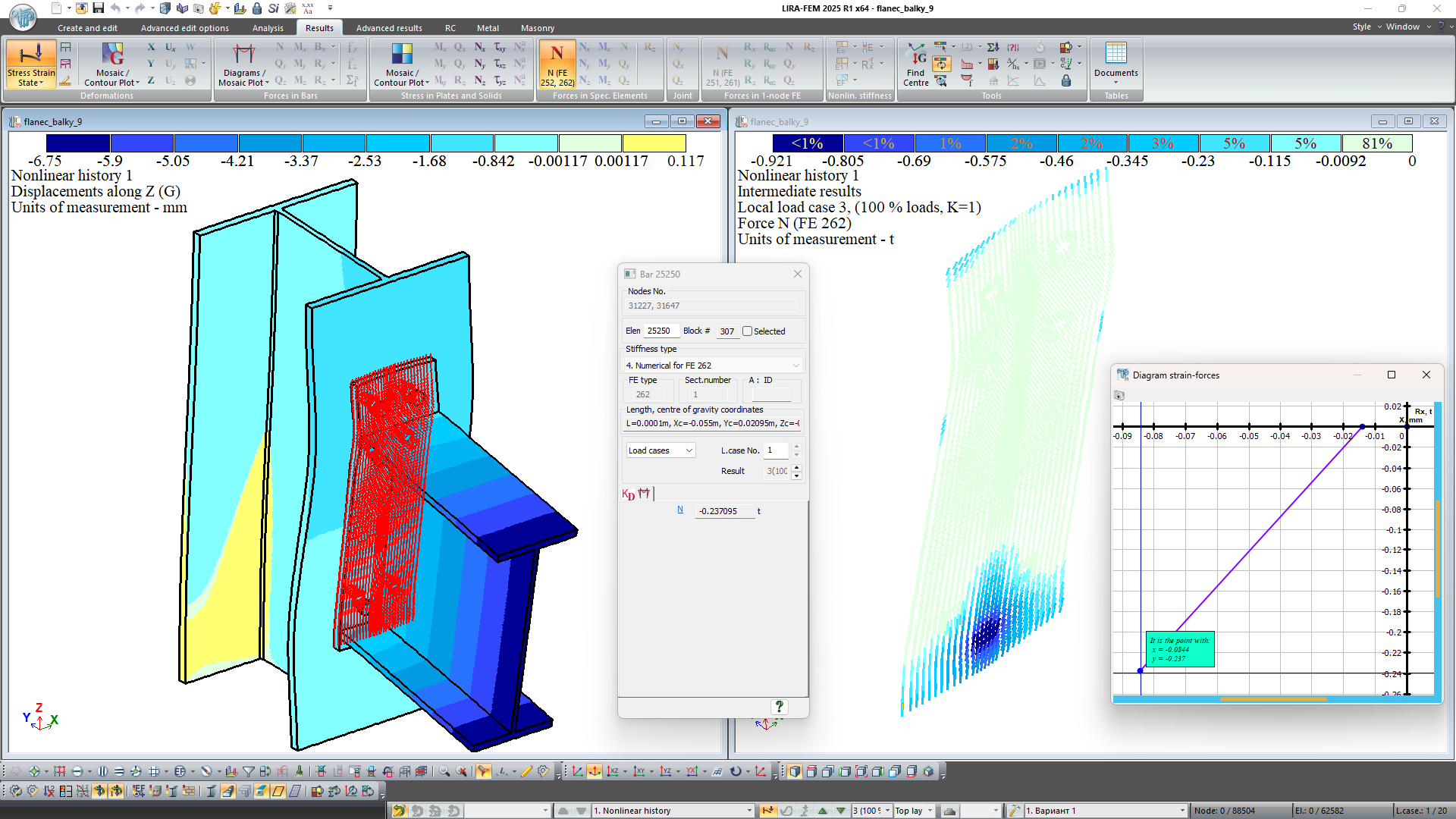
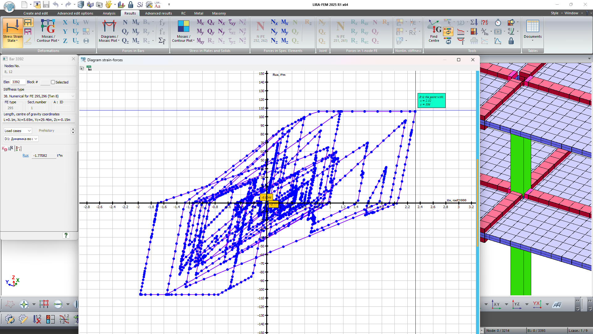
- Graphs can now be plotted for two-node and one-node special elements (FE of elastic springs: 51, 55, 56; 1-node FE of one-way spring with account of ultimate force: 251, 252, 255, 256; 1-node FE of one-way elastic spring with a gap between the structure and the spring: 261, 262, 265, 266; 1-node one-way FE of friction with a gap and accounting for friction between the structure and the spring: 263, 264).
-
It is now possible to save the "strain-force" diagrams for the special FEs in CSV format.
- A new cross-section type "Round Tube" has been added for specifying aluminum sections of bars using the aluminum database.
Generating and modifying the design model
- New types of loads:
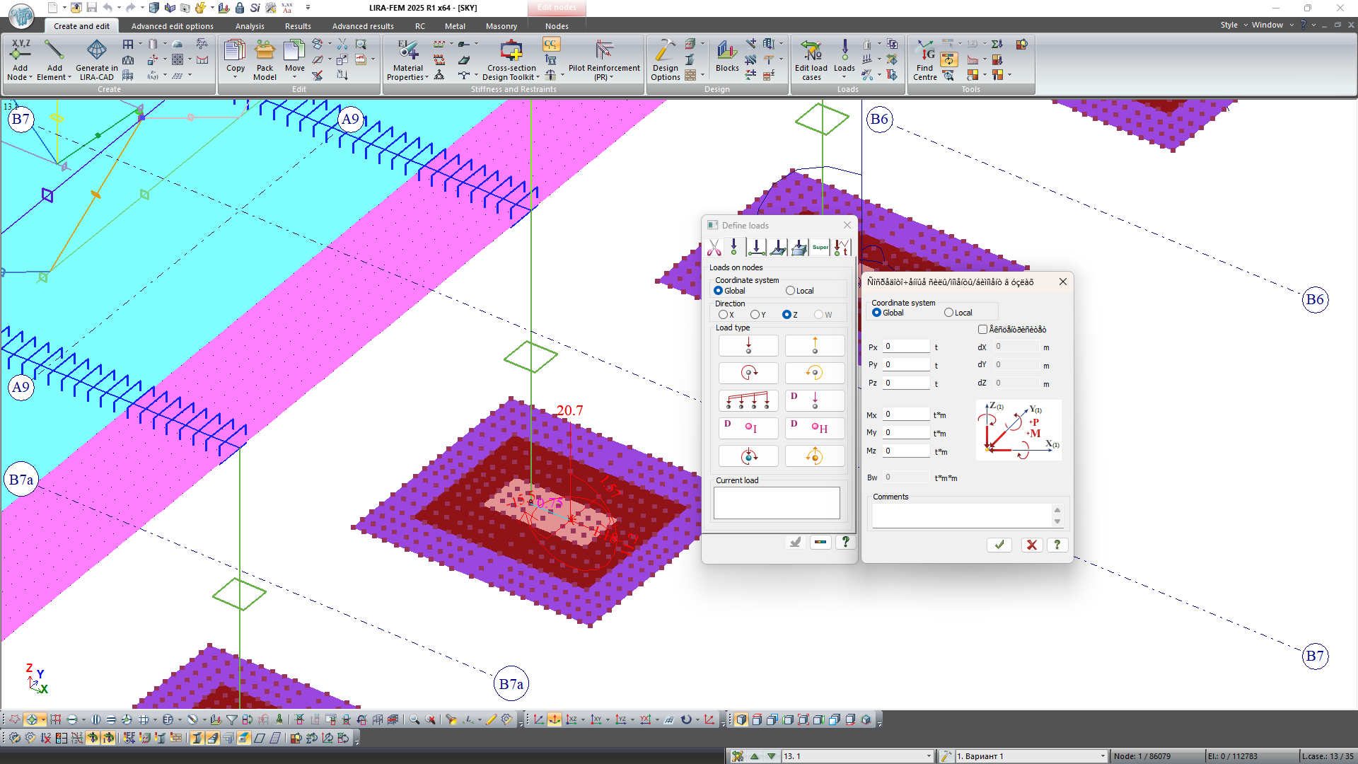
- A unified dialog box for setting, adjusting, or viewing the concentrated loads and moments along the direction of global or local axes, as well as the concentrated bimoment at the nodes. The combined load can be specified in two ways: by applying concentrated loads and moments directly to the node or by applying loads eccentricity relative to the node. Regardless of the chosen method, the combined load is always represented on the model as loads and moments.
- A unified dialog box for setting, adjusting, or viewing the specified translations and rotations along the local axes, as well as the specified warping at the nodes.
- Trapezoidal surface load for plates and solids.
- Trapezoidal load along the line (for bars).
- In the dialog box Surface load (load along the line and across the surface for plates and solids), a search parameter R has been added to configure the search area of finite elements for applying the surface load. It is used when adjusting load contours via input tables.
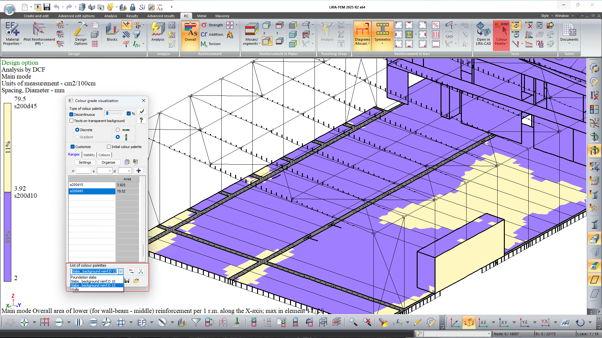
- The option to define sets of configured parameters for reinforcement colour palettes has been added.
- The option to replace one of the three material properties for reinforced concrete, steel, and aluminum/masonry reinforced structures has been added.
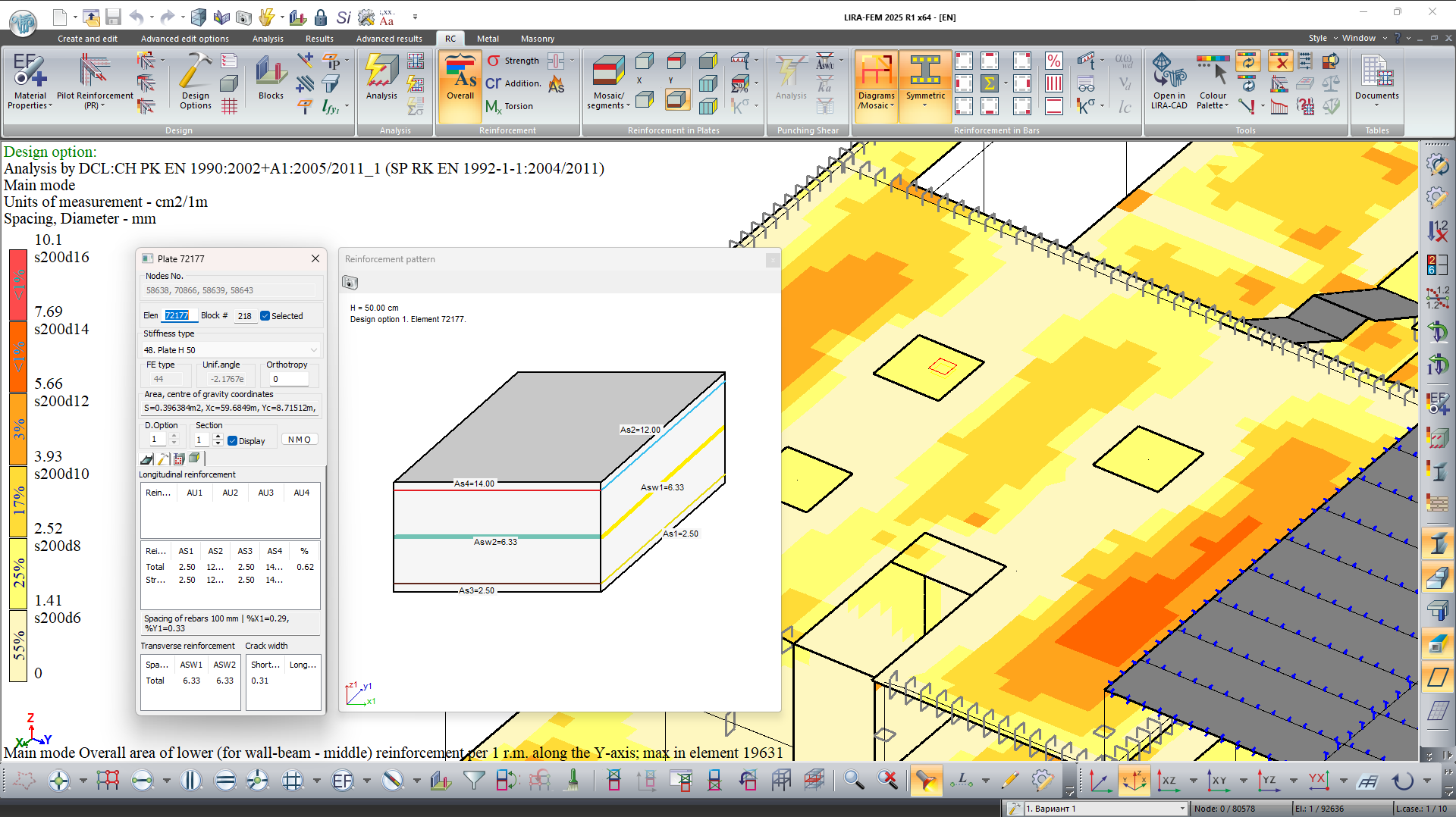
- A graphical visualization and documentation of the area of the selected longitudinal reinforcement at the section edges, as well as the area of transverse reinforcement for the specified plate in the current design option, has been implemented.
- The options to change the scaling of loads, the position of circles with tags of grid lines, force diagrams, and reinforcement for bars, mosaic plots for bars and nodes has been added via mouse wheel rotation while holding the Shift key. To revert to the default scaling factor, double-click the mouse wheel while holding the Shift key.
- A new cross-section type "Round Tube" has been added for specifying aluminum sections of bars using the aluminum database.
Generating and modifying the model
- New types of loads have been added:
- Warping at nodes accounts for the inadequacy of the cross-sectional plane of a bar; it is important when for analysis of the thin-walled structures.
- Bimoment at nodes takes into account the moment arising from a force distributed along the height of the cross-section.
- Bimoment by line is mentioned to model a distributed bimoment along an element of the structure.
- Dynamic modules have been added: (22) Impact, (23) Impulse, and (50) Earthquake (AzDTN 2.3-1-2010, modif. on Jan 01, 2014).
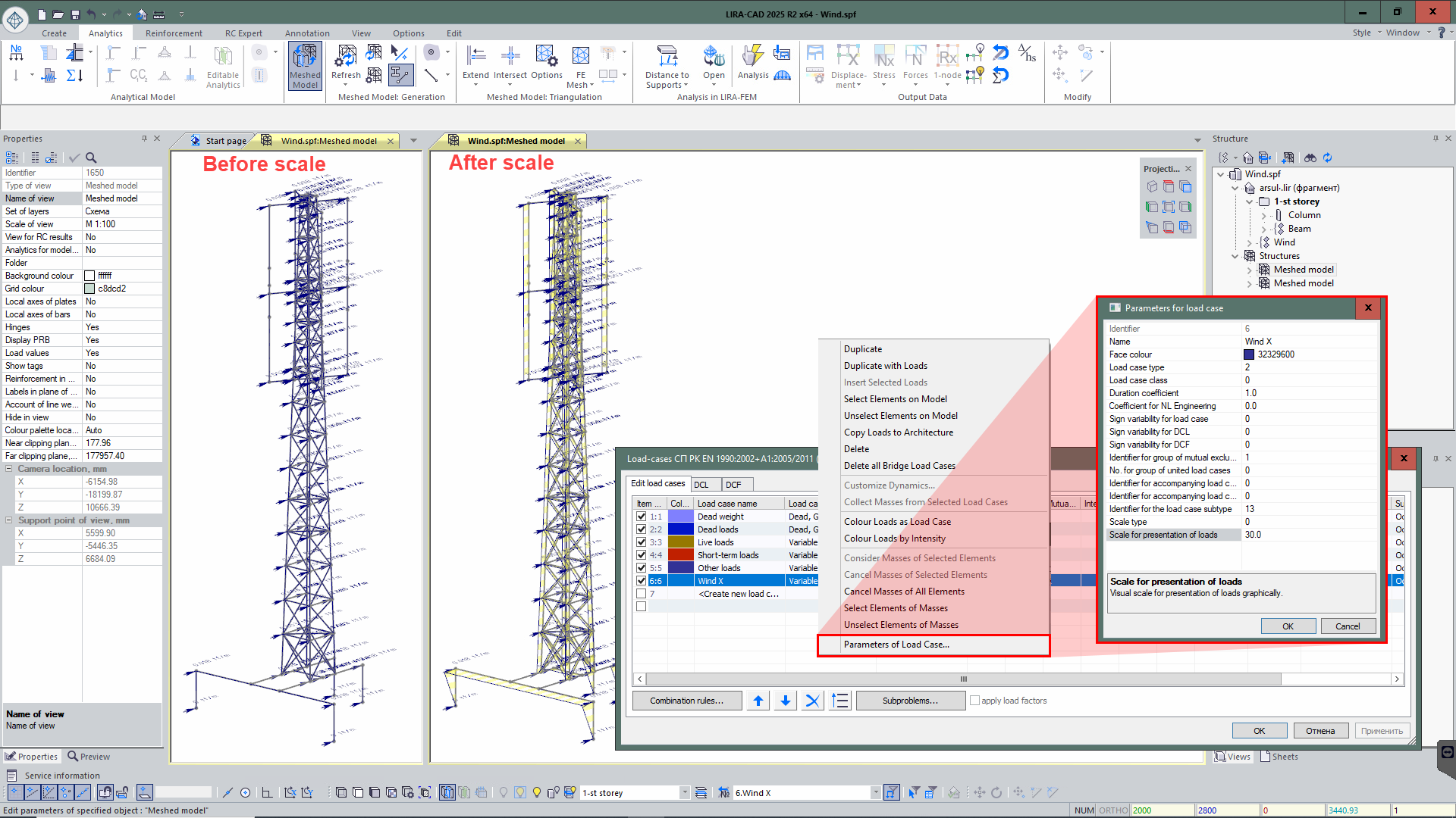
- In the "Parameters for load case" dialog box, the "Scale for presentation of loads" parameter has been added for the selected load. So, it is possible to change the scale of concentrated, linear loads and surface loads, ensuring a more illustrative visualization.
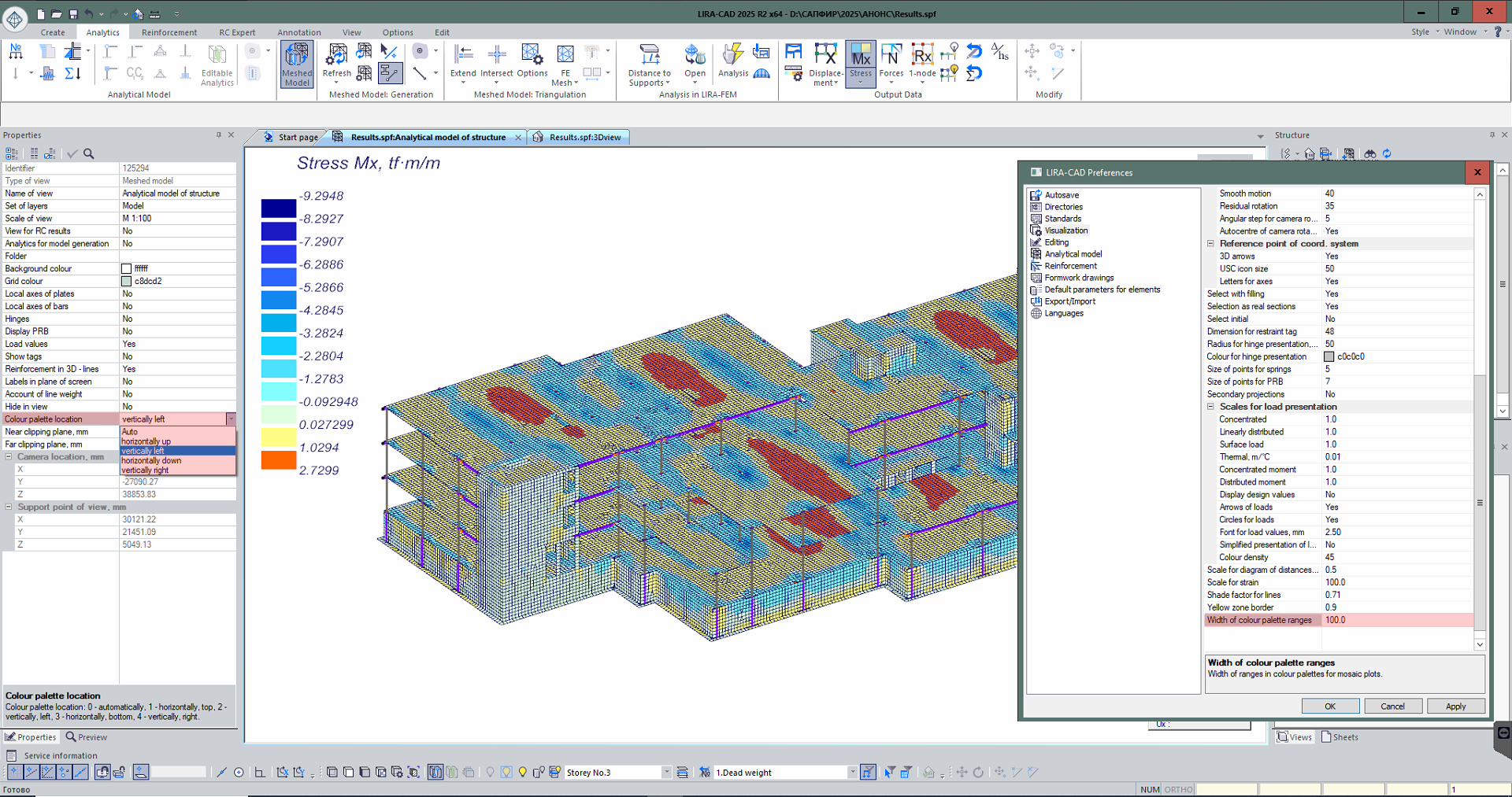
- Location of the colour palette for visualization of analysis results can be customized (in the LIRA-CAD meshed model), including for the visualization of analysis results in the "RC expert" module.
- An option for loads on the staircase has been implemented: to indicate whether the load is included in the additional load case during assemblage.
Components of BIM technology
- New input tables have been added for setting/correcting data: dissipation coefficients, Rayleigh coefficients, an enhancing coefficient Fvk, and custom mosaic data.
- The creation of a single block of axes at the project level—with alignment to selected building floors—has been added, replacing the axes block on every floor as in previous program versions.
- Import of the IFC model into the configured project template has been implemented.
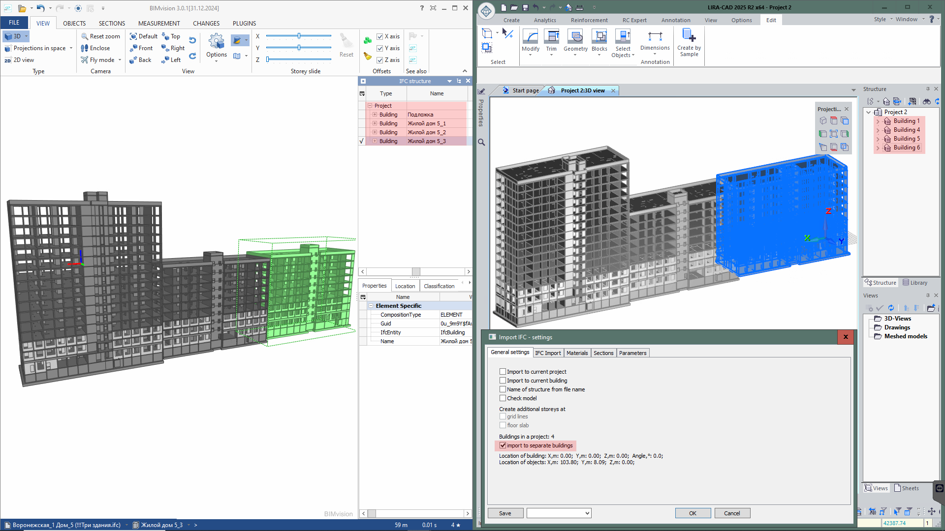
- When importing multiple buildings from IFC, the option to import them into separate buildings in LIRA-CAD has been added.
- The ability to import DWG floor plans into the current or a new project has been added.
- Automatic creation of openings along curved walls based on the DXF/DWG base for floor plans has been added.
- Display of the selected layer (instead of the List input name) in the “Layer Filter” node has been added.
- Improved recognition of the thickness of curved walls when constructing walls along the contour from the DXF/DWG base.
- Creation of openings along curved walls using the “Create windows at the intersection of walls and lines” node with the DXF/DWG base has been added.
- For the node “Advanced floor creation based on specified levels,” an option has been added to enable floor creation as in previous program versions (option “Upper floor levels – Yes”).
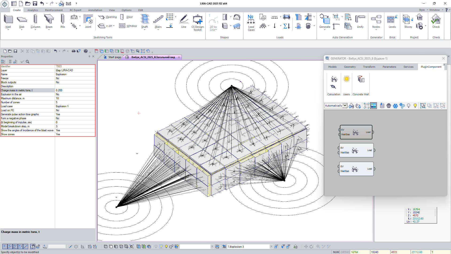
- Expanded functionality of the Blast node: an option has been added to account for or exclude the formation of a negative blast phase when constructing the graph of the explosive wave impulse’s effect (see blast analysis); for rear walls (those positioned at angles greater than 160° relative to the explosion epicenter), the gradual pressure increase caused by the shock wave’s flow along their back surface is taken into account.


