VERSION HISTORY
LIRA-FEM
- Components of BIM technology
- Generating and modifying the model
- Generating and modifying the design model
- Analysis options
- Tools for evaluation of object properties and analysis results
- Analysis & design of reinforced concrete (RC) structures
- RC Expert
- Analysis & design of steel structures
- Soil
- Cross-Section Design Toolkit
- Documentation improvements
Meshed Model
Generating and modifying the design model
- New types of loads:
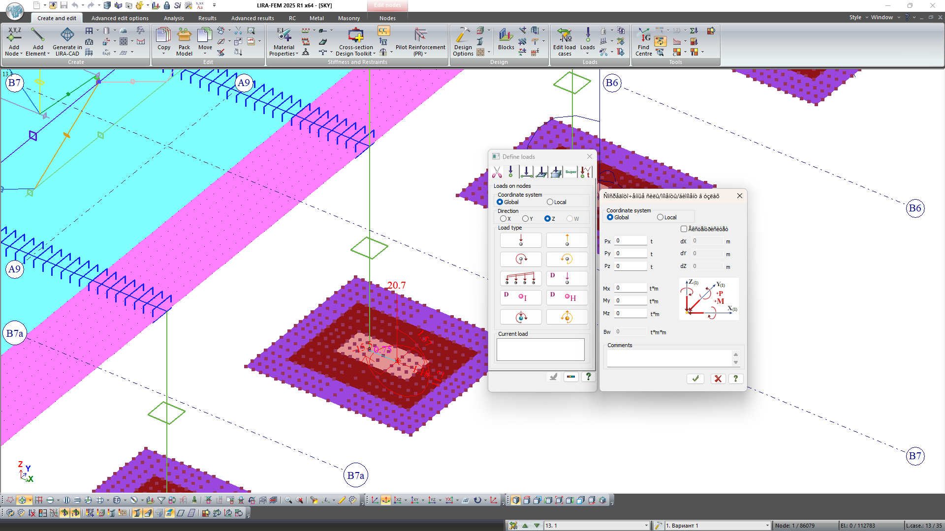
- A unified dialog box for setting, adjusting, or viewing the concentrated loads and moments along the direction of global or local axes, as well as the concentrated bimoment at the nodes. The combined load can be specified in two ways: by applying concentrated loads and moments directly to the node or by applying loads eccentricity relative to the node. Regardless of the chosen method, the combined load is always represented on the model as loads and moments.
- A unified dialog box for setting, adjusting, or viewing the specified translations and rotations along the local axes, as well as the specified warping at the nodes.
- Trapezoidal surface load for plates and solids.
- Trapezoidal load along the line (for bars).
- In the dialog box Surface load (load along the line and across the surface for plates and solids), a search parameter R has been added to configure the search area of finite elements for applying the surface load. It is used when adjusting load contours via input tables.
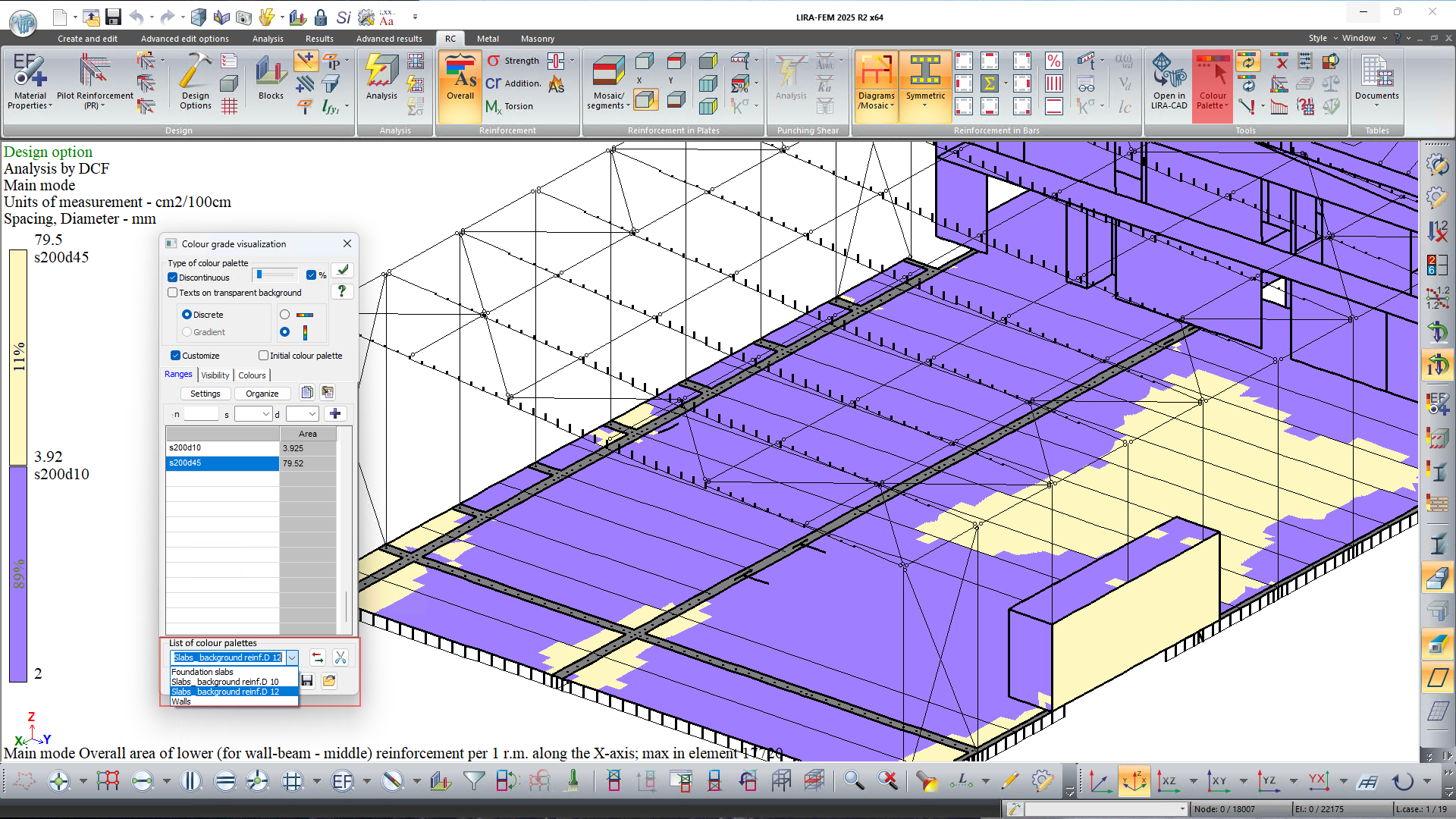
- The option to define sets of configured parameters for reinforcement colour palettes has been added.
- The option to replace one of the three material properties for reinforced concrete, steel, and aluminum/masonry reinforced structures has been added.
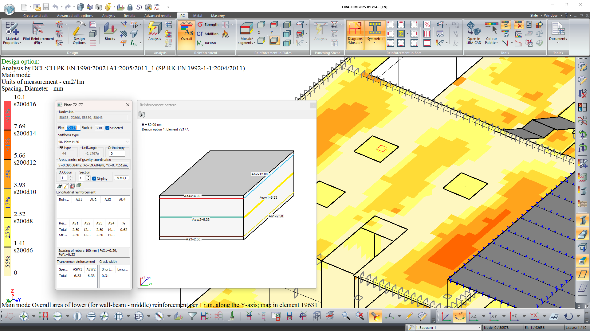
- A graphical visualization and documentation of the area of the selected longitudinal reinforcement at the section edges, as well as the area of transverse reinforcement for the specified plate in the current design option, has been implemented.
- The options to change the scaling of loads, the position of circles with tags of grid lines, force diagrams, and reinforcement for bars, mosaic plots for bars and nodes has been added via mouse wheel rotation while holding the Shift key. To revert to the default scaling factor, double-click the mouse wheel while holding the Shift key.
- A new cross-section type "Round Tube" has been added for specifying aluminum sections of bars using the aluminum database.
Further improvements related to the generation and modification of design model
New option to select the unloading method for each given piecewise linear material stress-strain diagram (14). This parameter is used for iterative physically nonlinear FE when modelling the process of material unloading with account of its nonlinear properties.
New commands that allow the user to create plates on the free faces of selected solids and on the surface of solids by the specified plane and angle of deviation. Such options will be helpful, for example, when creating target plates of plate analogue; elements of convective heat transfer on faces of solids of heat conductivity; when modelling 3D unlimited soil body, etc.
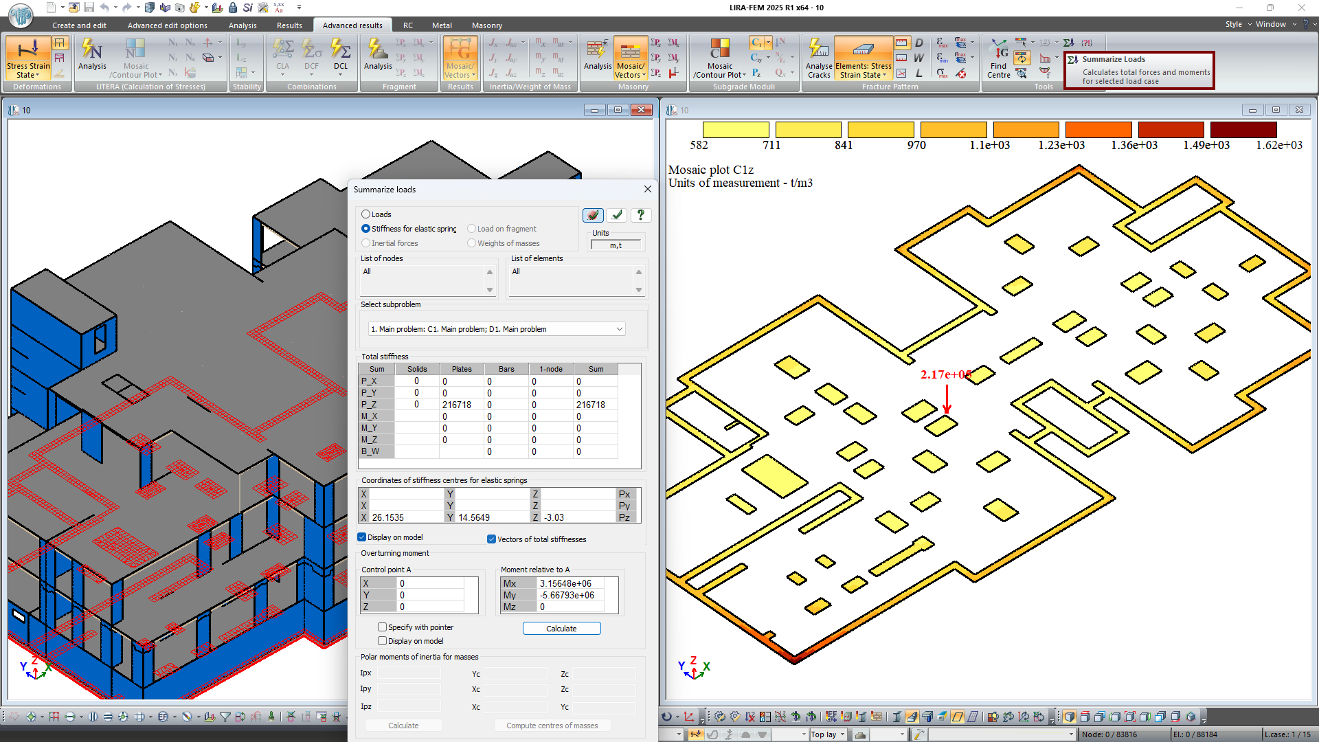
For plates and bars on an elastic foundation, the calculation of the total stiffness of the restraints along the Z-axis by C1z data is implemented (the initial specified stiffness may change after recalculation of the elastic foundation of the model attached to the soil model).
For 1-node elements FE 51, FE 56, FE 57, that model elastic foundations or piles, the specified or recalculated stiffness Rx, Ry, Rz is considered when calculating the total stiffness of restraints along the X, Y, Z axes.
Note. When the stiffnesses of restraints are summed up, appropriate sets of subgrade moduli C1z (property set C) and sets of coefficients to the modulus of elasticity kE (property set D) are considered according to the selected subproblem. The stiffnesses of the 1-node elements FE 51, FE 56, FE 57 are summed up with account of the corresponding kE coefficients.
New options to display on the model the following data:
- comments on the assigned stiffnesses;
- contours for uniformly distributed load for plates and solids;
- overturning moments relative to a specified point;
- numbers of assemblage groups;
- change in the size of the colour zone when generating mosaic plots of properties and results at nodes;
- directions of the principal axes of the bars calculated as a result of physically nonlinear analyses.
In the dialog box for creating design options, there is a new command that allows you to create a new design option for the model based on the template of the selected design option.
New command to display in a new window the nodes and elements previously selected on the model.
Now it is possible to copy and add (from the Clipboard to the current problem) materials for masonry reinforced structures for all building codes and design options.
When design model is automatically divided into structural blocks Plate, Wall, there is a new option to consider gaps in their contours (if there is no common nodes) in one plane. This option also affects the generation of a regular Block.
New option to automatically generate structural blocks (column, beam, slabs) when creating a 3D frame. It is also possible to automatically generate grid lines and elevations.
Import of arc grid lines from the LIRA-CAD module is supported now. The arc grid lines can be edited using the following tools: rename, define Z-axis snap, and delete. It is possible to check the presentation and parameters for selection of nodes and elements when clicking on the tag of the arc grid line or when selecting several grid lines with the rectangular 'selection window'.
New command to delete all grid lines and height elevation on the model.
New option to rename height elevation to the existing functionality for renaming grid lines.
When you add bar elements and divide bars into several parts, there are commands that allow you to unite new elements into a structural block and structural element.
To check the input data of structural elements, there is a column with the total length of the bars included in the structural elements.
When selected bars are united into one, there are options that enable you to check the coincidence of StE types, the offsets, restraints and PRBs. If the corresponding checkboxes are selected, the chain of selected bars will be united only in the regions where the corresponding parameters of bar coincide or in regions between nodes with restraints or PRBs.
For more convenient visualisation of the plates, a projection on the XOY-plane (top view) is added; the Y-axis is horizontal here.
New option to sort by parameters in the dialog box for perfectly rigid bodies.
Now it is possible to place a rectangular grid in all four quadrants of the plane relative to the centre of the grid.
Modelling the construction process
Assemblage stages may be generated automatically based on height elevations. With this option, assemblage stages are created, and lists of assembled elements (that are located between neighbouring elevations and/or at the level of the lower/upper elevation) are generated automatically.
For problems in which erection process is modelled, now there is an option to organize the list of load cases. It is now possible to move load cases up or down in the list, and to insert a new load case above existing load cases in the list.
Additionally, the assemblage stages can be moved up or down. In this case, the following data is automatically transferred: the numbers of assembled or disassembled elements, the parameters and coefficients that influence the concrete's strength and modulus of deformation, and the coefficients that account for extra load cases during the assemblage stage. There is no change in the order of load cases.
Time history analysis
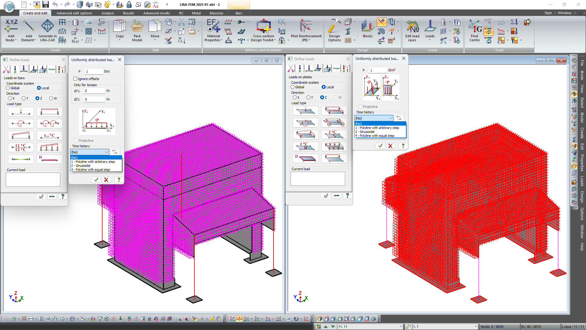
The new option to define the dynamic uniformly distributed load on bars and plates for time history analysis. The following diagrams for such loads are implemented: piecewise linear load (broken) with arbitrary step; sinusoidal load; piecewise linear load (broken) with uniform step.
Now it is possible to carry out analyses using the direct dynamic method (Time History Analysis system) for several dynamic load cases within one design model. Moreover, an algorithm has been implemented to remove restrictions on the number of integration steps. It enables the user to evaluate different scenarios of dynamic load and carry out analyses with higher accuracy, which is especially important for analyses of buildings and structures on earthquake loads, air shock wave effects, etc.
The user could also carry out an analysis on progressive collapse within a single design model for several scenarios of local failures in elements of structure. The analyses are carried out by the dynamic method of direct integration of the equations of motion in time (Time History Analysis system) in linear and nonlinear statement. This method allows the user to take into account damping effects.
New option to calculate the temperature field for problems with transient heat transfer analysis for several scenarios of time-varying temperature within a single design model.
New option to determine mass (α) and stiffness (β) proportionality constants to account for Rayleigh damping by specifying frequencies and damping coefficients.
Equivalent cross section
In analysis of reinforcement and/or analysis of pilot reinforcement in RC and composite (RC & steel) elements, selection and check of cross-sections of steel elements, the building codes are oriented towards standard types of cross-sections. For an arbitrary cross-section, it is only possible to obtain a picture of the stress-strain state.
New system to create an equivalent cross-section (beam, T-section with a flange at the top or bottom, I-section, box, cross, or channel) from an arbitrary cross-section based on geometric properties. A file created in the Cross-section Design Toolkit module defines the initial cross-section.
The following characteristics are approximated for a specified section: area, principal moments of inertia and section modulus. The user-defined values of weight coefficients are taken into account (by default, all weights are equal to 1).
An equivalent cross-section is an abstract description of stiffness; it approximates the behaviour of a structure or element under load. Such a cross-section has the same geometric and mechanical properties that allow to adequately describe the behaviour of a structure or element under different loading conditions.
Orthotropy of shape
A new tool Orthotropy of shape is mentioned to determine and the elastic properties for structurally orthotropic plates of various configurations. The functionality covers a wide range of slab types including:
- slabs with single- and double-sided unidirectional ribs;
- slabs with single-sided bi-directional ribs;
- unidirectional and bi-directional box-shaped slabs;
- beam system;
- corrugated plate (trapezoidal or wavy);
- slab on corrugated plate taking into account the steel material;
- hollow slab (with round or oval holes).
Structural orthotropy is used in finite element design models in order to more correctly represent the behaviour of real structures while accounting for their anisotropic features. This is especially important for the design of bridges, metal structures, and other complex engineering objects where optimisation of stiffness and strength is required.


