Design combinations of forces (DCF) and design combinations of loads (DCL)
Design combinations of forces (DCF) and design combinations of loads (DCL). How to define DCF and DCL in LIRA-FEM* software. The difference between DCF and DCL. Several tables for DCF and DCL.
- Finite element analysis
- Static analysis
- Dynamic analysis
- Nonlinear analysis
- Seismic analysis
- Design combinations
- Frame analysis
- Beam analysis
In the LIRA-FEM (LIRA-SAPR) software it is possible to carry out FEA by:
- load cases (all load cases are mutually exclusive, i.e. in analysis of RC and steel elements, design forces will be taken from each individual load case);
- design combinations of forces (DCF);
- design combinations of loads (DCL).
Now a few notes about the difference between DCF and DCL.
Design combinations of forces (DCF)

In the LIRA-FEM program, design combinations of force (DCF) are generated automatically.

When DCF are calculated, it means the program will find out the extreme values of those components of the stress-strain state that serve as criteria for the greatest danger of this stress-strain state. In this case, the specific features of various FE types are taken into account, and the number of considered DCF is significantly reduced.
To put it simply, the program determines the load combination and point in the cross-section where the greatest force or stress will occur; only these extreme values are saved.
Since the extreme values of forces and stresses may be located at different points in the cross-section in different elements of the model, the output data for the calculation will not contain nodal displacements.
Criteria by DCF for bars
The extreme values of normal and shear stresses calculated at certain points of the reduced rectangular cross-section as well as the extreme values of forces in the cross-section are taken as dangerous criteria of the DCF for bars.

For normal stresses, the following formula is applied:
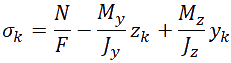
where k Ц the point of bar section (k = 1...9).
This formula is converted as follows when
![]() :
:
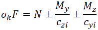
where cyi and czi Ц core distances in the core cross-section (i = 1,2). This approach makes it possible to determine the extreme normal stresses in ANY cross-section and reduce the cross-section to a rectangular shape.
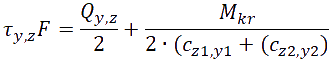
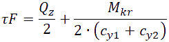
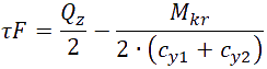
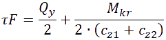
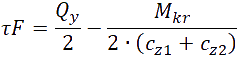
For the shear stresses, an approximate formula is applied:
The stresses calculated by formulas (2) and (3) are displayed in Table 1 for each point of the section. The sign convention for the forces is applied.
Table 1. Formulas for calculating the stresses at the points of rectangular cross-section.
|
Section point No. |
Normal stress |
Shear stress |
|
1 |
|
- |
|
2 |
|
- |
|
3 |
|
- |
|
4 |
|
- |
|
5 |
|
|
|
6 |
|
|
|
7 |
|
|
|
8 |
|
|
In addition to the normal and shear stresses, the extreme values of the following parameters are calculated: the longitudinal force and each of the shear forces, horizontal and vertical reactions of the elastic foundation, the bending moments.
46 DCF values are selected for the bar section.
The numbers for DCF criteria for the bars and the corresponding stresses and forces are presented in Table 2.
Table 2. DCF criteria for bars
|
Criterion No. |
1 |
2 |
3 |
4 |
5 |
6 |
7 |
8 |
9 |
10 |
11 |
12 |
|
Value |
σ1+ |
σ1- |
σ2+ |
σ2- |
σ3+ |
σ3- |
σ4+ |
σ4- |
𝜏7+ |
𝜏7- |
𝜏8+ |
𝜏8- |
|
Criterion No. |
13 |
14 |
15 |
16 |
17 |
18 |
19 |
20 |
21 |
22 |
23 |
24 |
|
Value |
𝜏5+ |
𝜏5- |
𝜏6+ |
𝜏6- |
N+ |
N- |
σ7+ |
σ7- |
σ8+ |
σ8- |
σ5+ |
σ5- |
|
Criterion No. |
25 |
26 |
27 |
28 |
29 |
30 |
31 |
32 |
33 |
34 |
35 |
36 |
|
Value |
σ6+ |
σ6- |
Qy+, N+ |
Qy-, N+ |
Qy+, N- |
Qy-, N- |
Qz+, N+ |
Qz-, N+ |
Qz+, N- |
Qz-, N+- |
Ry+ |
Ry- |
|
Criterion No. |
37 |
38 |
39 |
40 |
41 |
42 |
43 |
44 |
45 |
46 |
- |
- |
|
Value |
Rz+ |
Rz- |
My+ |
My- |
Qz+ |
Qz- |
Mz+ |
My- |
Qy+ |
Qy- |
- |
- |
DCF criteria for plates
For elements of plane stress state, plates and shells, the stresses determined by Wood-Armer method according to the following formulas are taken as the criterion:
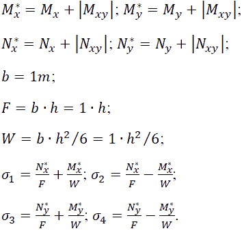
The numbers for DCF criteria for the plates and the corresponding stresses are presented in Table 3.
Table 3. DCF criteria for plates
|
Criterion No. |
1 |
2 |
3 |
4 |
5 |
6 |
7 |
8 |
9 |
|
Value |
σ1+ |
σ1- |
σ2+ |
σ2- |
σ3+ |
σ3- |
σ4+ |
σ4- |
Nx*+ |
|
Criterion No. |
10 |
11 |
12 |
13 |
14 |
15 |
16 |
17 |
- |
|
Value |
Nx*- |
Ny*+ |
Ny*- |
Qx+ |
Qx- |
Qy+ |
Qy- |
√(Qx2+Qy2) |
- |
DCF criteria for solids
The extreme stress values are considered as criterion for determining DCF for solids. The numbers of the criteria and the corresponding stresses are presented in Table 4.
Table 4. DCF criteria for solids
|
Criterion No. |
1 |
2 |
3 |
4 |
5 |
6 |
7 |
8 |
9 |
10 |
11 |
12 |
|
Value |
Nx+ |
Nx- |
Ny+ |
Ny- |
Nz+ |
Nz- |
Txy+ |
Txy- |
Txz+ |
Txz- |
Tyz+ |
Tyz- |
DCF criteria for special FE
The extreme force values are considered as criterion for determining dangerous combinations in special elements (one-node FE 51, 56 and two-node FE 55).
For FE 51, 55 and 56, the numbers of the criteria are accepted from 1 to 12, they correspond to the force indexes in the FE.
For the out-of-contour elements of soil (FE 53, 54), the DCF are not calculated.
The following regulations are supported in the DCF calculation:
- DBN B.1.2-2:2006 (Ukraine)
- SNIP 2.01.07-85* (USSR)
- SP 20.13330.2011/2016 (RF)
Design combinations of loads (DCL)

The DCL system is mentioned to calculate displacements at nodes and forces (stresses) in elements from standard and arbitrary linear combinations of loads. The standard linear combinations are taken to mean combinations regulated in normative documents.

The following regulations are supported in the DCL calculation:
- DBN B.1.2-2:2006 (Ukraine)
- Eurocode (EU)
- EN 1990-2011 (EU)
- SP RK EN 1990:2002+A1:2005/2011 (Kazakhstan);
- TKP EN 1990-2011*(02250) (Belarus)
- STB EN 1990-2007 (Belarus)
- ACI 318-95 (USA)
- IBC-2000 (USA)
- BAEL-91 (France)
- SNIP 2.01.07-85* (USSR)
- СП 20.13330.2011/2016 (RF)
What is the fundamental difference between DCF and DCL?
The DCF system goes through all possible load combinations and the output data will contain only the most unfavourable ones, whereas in the DCL system, the output data will contain all user-defined combinations.
Why do I define both the DCF table and DCL table in the same problem
To evaluate the strain of the building structure and the displacements at nodes of the model, we carry out calculation by design combinations of loads (DCL).
For example, there are about 30 load cases in the model, 10 of them are dynamic load cases, and each dynamic load case has 10 mode shapes. The total is 120 load cases. To reduce the time required for calculation of forces for subsequent design, in this case it is reasonable to calculate by design combinations of forces (DCF).
Is it possible to set up more than one DCF and DCL table in the same problem?
In LIRA-FEM problem, it is possible to specify several DCF tables and DCL tables. Multiple tables are required when it is necessary to calculate different structural elements with account of different responsibility factors, when it is necessary to perform comparative analysis of structures according to different building codes. Additional DCL tables may be generated to evaluate the deformation of design model, i.e. they are not used in the structural design.
What is the meaning of the acronym DCF and DCL?
«DCF» - design combinations of forces;
«DCL» - design combination of loads.
Evaluate the software
If you have any doubt, download the Demo version and evaluate the program or contact our Support Team for more details.