

VERSION HISTORY
LIRA-FEM
- Components of BIM technology
- Generating and modifying the model
- Generating and modifying the design model
- Analysis options
- Tools for evaluation of object properties and analysis results
- Analysis & design of reinforced concrete (RC) structures
- RC Expert
- Analysis & design of steel structures
- Soil
- Cross-Section Design Toolkit
- Documentation improvements
LIRA-FEM 2025 R2 Update 3
Important.Resolved a potential CodeMeter licence malfunction that could occur after installing Windows 11 updates KB5074105 and KB5077181 (January–February 2026)
More
LIRA-CAD
-
Fixed error when editing opening contour in load specified across the area.
-
Corrected load application from spaces containing openings. Previously, loads were applied to the centre of the opening.
-
Eliminated duplication of loads on stair stringers.
-
Resolved potential issues when generating meshed model containing Prism objects.
-
Fixed error in subdivision of inclined columns by storey levels. Generated columns were shifted from the original central axis of the column.
-
Fixed error in retrieving parameter M_FEA_BARRA_FORM via API.
-
Fixed saving of plate intersection search tolerance. The specified value was previously reset after each update of meshed model.
-
Corrected assignment of load to erection stages. Loads intended as post-erection were incorrectly included in erection stages.
LIRA-FEM
-
Fixed potential crash in SOIL system when model contained permafrost soil properties.
-
Fixed an issue where the application could become unresponsive during iterative calculation of elastic foundation parameters C1/C2 in models with ten or more dynamic load cases.
-
For problems with account of erection stages, corrected consideration of load combination factors when generating design combinations of loads for punching shear.
-
When generating the results table "Load on fragment" in problems with nonlinear load histories, generation of history names is corrected.
-
For steel built-up sections, eliminated discrepancies between ULS results in batten plates in analysis by elements and by individual design sections.
-
Clarified application of safety factor ɣn defined in DCF and DCL parameters when determining punching shear design forces.
-
Fixed generation of forces for steel joint design by DCF when normative loads are defined in the model.
-
For L-shaped reinforced concrete sections, eliminated discrepancy in coordinates of defined reinforcement bars calculated in the main model and in the local mode of reinforcement.
LIRA-FEM 2025 R2 Update 2
LIRA-CAD
- Restored option to specify a fixed step for triangulation points in slabs via the properties of the bar analogue.
- Fixed cases of program failure when transferring a model to LIRA-FEM.
- Fixed bug: the load from a space was duplicated if a slab with an opening was located below it and another slab was placed within that opening.
- Restored option to consider the openings in spaces that are interpreted as loads.
- Improved the conversion function: walls are now converted into beams with the beam axis coinciding with the axis of the original wall.
- Fixed bug: when the Real volumes parameter is activated, it caused the option for perfectly rigid body (PRB) generation to remain active even after the parameter was changed.
- Fixed bug: the design material properties of capitals and column bases were not transferred to or assigned in LIRA-FEM.
- Fixed bug: when column bases and capitals are selected in groups in the Parameters dialog box.
- Fixed bug: incorrect object links when copying nodes in the Generator system.
- Improved performance of the shader-based graphics on professional NVIDIA graphics cards.
- Restored option to generate the load with the custom node Linearly distributed load on objects (Services tab).
- Fixed bug in importing cross-sections in *.saf format in case the section width and height were swapped.
- Fixed bug in transferring Triangulation and Stiffness parameter values for Plate object to the design model.
- Fixed bug in selecting Spaces after the *.ifc import via the Generator system.
- Fixed bug: incorrect generation of impulse diagram by the Blast node in certain cases.
- Fixed bug: program failure that occurred when the Skews command was activated.
- Extended program response to changes in units of measurement across multiple systems of the program, including Elastic support, Snow mound, Spring, Load summation, etc.
- Fixed bug: program failure that occurred when working with column bases.
- Fixed bug: incorrect behaviour of an opening in an inclined slab.
- Fixed bug: in replacing a Special element with a Perfectly Rigid Body (PRB) when the model is transferred to LIRA-FEM.
- Fixed bug: incorrect calculation of corner reinforcement in the Reinforcement type dialog box.
- Enhanced the algorithm for collecting wind loads on side surfaces of the building.
- Improved behaviour of openings with non-standard geometry in walls.
- Fixed bug: program failure that occurred when checking pit alignment.
- Fixed bug: roof triangulation when using the Proxy object interpretation for loads.
LIRA-FEM
- Redesigned finite elements for thick slabs so that the shear locking is eliminated. As a result, correct behaviour of thick slabs is ensured for small thickness-to-span ratios typical of thin slabs, without loss of analysis accuracy.
- For the METEOR system, corrected load case numbering in the text result tables for DCF and DCL(c). It occurred when combining results of standard analyses with time-history analyses.
- Fixed data sorting in columns of input tables (column data were not sorted if the column No. exceeded the number of rows in the table).
- Fixed bug: program failure when checking pilot reinforcement (PR) in cases where reinforcement pattern in the section was defined using the condition "distance to gravity centre of reinforcement - from materials".
- Fixed bug: program failure after converting super-elements into fragments of design model and performing model packing.
- Fixed downloading of problem file that contains stiffness for orthotropic plates specified via the elasticity matrix.
- Corrected procedure for a data saving in the Borehole table dialog box (in the SOIL system) when there is a deleted comment row.
- Clarified relation between the section class and the utilization ratio for local buckling of flanges and webs according to SP RK EN 1993-1-1:2005/2011.
- Fixed bug: in determining the DCL table number during iterative refinement of pile stiffness.
- A shortened name for calculation type is implemented in materials for reinforced concrete (RC) plates.
- Restored option to check and select the steel sections composed of double channels with a gap between the webs.
- Accelerated lengthy packing for a large number of unique loads (with load-time histories) in problems with time history analysis.
- Fixed bug: program failure when synchronising result views for two problems with time history analysis.
- Fixed bug: after renaming a problem in the Model type dialog box, data in the Report Book remained linked to the previous directory on disk.
- For DBN B.2.6-198:2014, corrected the algorithm for checking steel sections, and refined the overall stability analysis for built-up laced columns made of angles.
- For DBN B.2.6-198:2014, fixed the assignment of ultimate slenderness values when changing element types of steel trusses and columns.
LIRA-FEM 2025 R2 Update 1
- Restored import of spaces from IFC files (spaces above the first floor were not imported).
- Fixed bug where only floors were generated during IFC import, but the structural objects of the building were not loaded.
- New command Allow Intersections to cancel the No Intersection command. The command supports the work with a group of selected objects. Previously, the prohibition of intersections could only be removed through Manage Links dialog box.
- Fixed bug: the height of the retaining wall changed if there is a pit with walls in the model.
- Fixed bug: the specified levels were not transferred when a building is copied from one model to another.
- Improved algorithm for generating a triangulation mesh at the intersection of walls, and at the intersection of walls and slabs.
- Improved algorithm for generating perfectly rigid body (PRB) in the zone of intersection between slabs and walls.
- Improved algorithm for generating the combined behaviour of walls and slabs in cases where the wall is very close to the slab edge but not absolutely parallel to it.
- Fixed bug: program failure when saving a project in previous version of LIRA-CAD module.
- Fixed bug: program failure when changing parameters of a load-bearing wall to load type and assigning a user-defined material.
- Fixed bug: program failure when interacting between LIRA-CAD and Grasshopper nodes.
- Fixed bug: the loads were duplicated in floor slabs, stairs, and prisms when transferring a model from LIRA-CAD module.
- Fixed bug: the loads (forced displacement along a line, bimoment along a line, harmonic load at a node, and warping) were not transferred to LIRA-FEM.
- Fixed bug: incorrect switching between project floors.
- Fixed bug: in the blast node, modified algorithm for applying loads to objects of the model.
- Fixed bug: columns were lost when saving a project to SAPFIR-3D 2021
- Fixed bug: a beam (modelled as a bar analogue with plates in the horizontal plane) generated an incorrect stiffness description in LIRA-FEM
- Fixed bug: special elements cannot be transferred to LIRA-FEM
- Fixed bug: the procedure for export of the model to an IFC file was slowed down.
- Enhanced auto-snap of loads from space to floor slabs and inclined slabs (loads were incorrectly linked to inclined slab).
- New option to insert a vertex into a circle (in wall and slab).
- Enhanced generation of wind load on floor slabs, displacement of a building along the height (that is specified in the building properties) is considered.
- Added option: rotation angle of the building (specified in the building’s properties) is considered in the following cases:
- for the meshed model of the retaining wall;
- for a single grid line in the meshed model;
- when generating a pit, copying from a base point, and mirror copying a pit.
- Improved link between punching analysis results and the floor slab when importing analysis results of reinforcement from LIRA-FEM. Previously, punching results from the floor slab may be incorrectly displayed on the view with reinforcement in foundation slab in cases where the floor slab and foundation slab were located on the same storey.
- Corrected presentation of rebar dowels from the foundation slab to the column when the base point of the column section is shifted relative to the centre of mass.
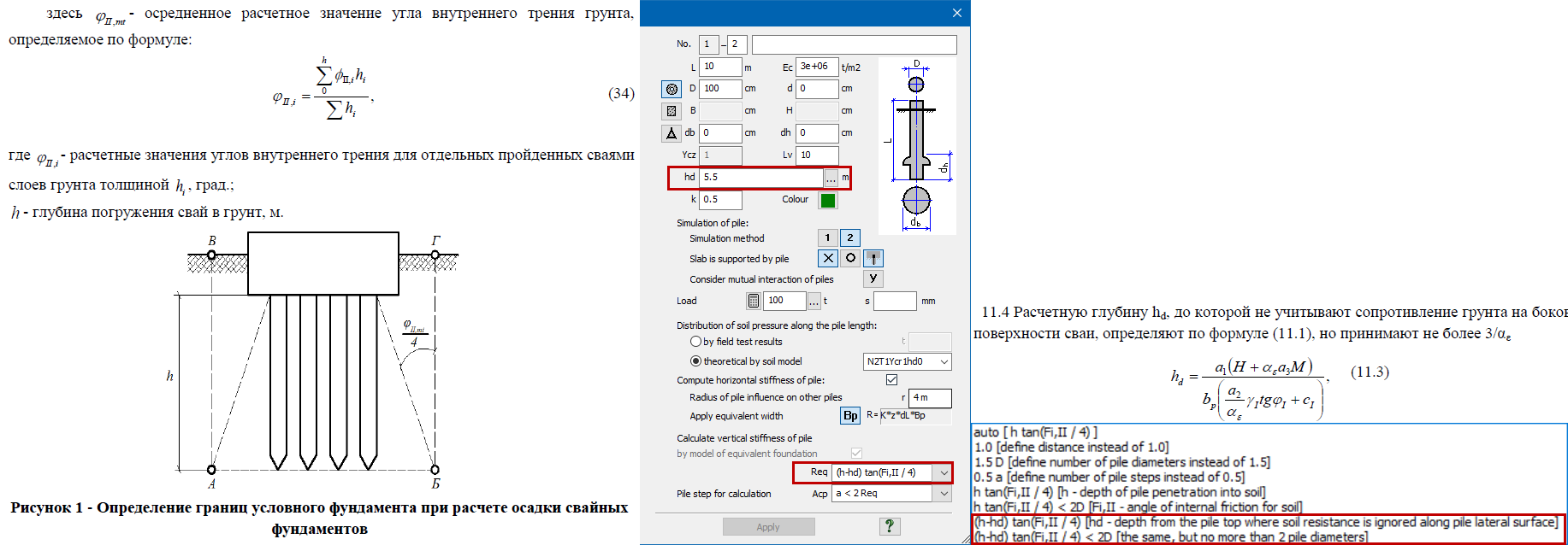
- Modified account of the hd parameter in the calculation of piles.
- Modified calculation of the Sp parameter with account of the pile widening.
- Modified option: group editing of elasticity matrix parameters when specifying the stiffness of orthotropic slabs with the elasticity matrix. The Undo/Redo commands are also modified.
- Modified procedure for updating the assigned values steel stiffness for profiles selected based on the results of steel analysis.
- Fixed bug: specified coordinates of the torsion centre for an unequal angle were lost when the steel tables were edited manually.
- Fixed bug: finding the moment of inertia for a cross (section) composed of angles.
- The warning message issued when the soil settlement Sp resulting from soil punching under the equivalent pile foundation is zero has been revised for clarity.
- When analysing piles, the computation of the Fd parameter has been refined for cases where no seismic action is defined in the model.
- When analysing a soil model with piles, the consideration of loads from excavated soil has been refined.
- Fixed bug: when creating a load from constructed soil.
- Accelerated transfer of unification groups of steel elements to the local STC mode for calculation of deflection.
- Fixed bug: the area of punching shear reinforcement was displayed incorrectly in the Information about node dialog box in case of an additional punching shear load contour in the node.
- The warning message issued when calculating the reserve factor for reinforcement according to SP PK EN 1992-1-1:2004/2011 (Republic of Kazakhstan) has been revised for clarity.
- When viewing standard tables with analysis results, the TXT and HTML formats have been restored.
- When calculating design combinations of forces (DCF), the generation of the E1 combination group has been restored (to account for progressive collapse).
- Restored option: to set the Req parameter in pile diameters when calculating piles.
- Modified calculation of pile stiffness when contours of equivalent foundations overlap.
- The handling of mutually exclusive load cases in the 'Combinations of loads and actions' system has been refined.
- Restored option: to create posters from the Report Book.
- Fixed bug: reconnecting to the LiraFEM.exe when using LIRA-FEM API objects.
- Fixed bug: possible incorrect transfer of forces in analysis of reinforcement in RC slabs.
- In check of RC sections by ultimate limit states, the 'Clarify pattern of crack propagation' parameter has been refined.
- Restored option: to display the graph of dynamic coefficient for dynamics modules 57 (DBN B.1.1-12:2014, Ukraine) and 58 (SNIP KR 20-02:2009, Kyrgyzstan).
- Fixed option: to find out the average value of uneven surface load when generating a mosaic plot with load values.
- Fixed bug: possible failure of Autodesk Revit when exporting an analytical model to LIRA-FEM.
- Restored option: to display analysis results for steel section by the serviceability limit state for several design options.
- Added option: to control the correctness of nodal loads when importing a meshed model created in LIRA-CAD module.
- Fixed bug: in calculating combinations of loads and actions when several DCL tables are generated from a single Combinations of loads and actions table.
- Fixed an infinite loop in the analysis of reinforcement for bar elements with a variable number of intermediate reinforcing items (DBN B.2.6-98:2009).
- Clarified identifier and snap for the punching shear contours of floor slabs and the load contours of foundation slabs created in LIRA-CAD module.
- Analysis of some steel sections is accelerated, improved accuracy in dividing steel structural elements into sub-elements.
- Values of calculated moments of inertia for some steel sections have been refined.
- Fixed bug: in calculating soil resistance when converting imported loads to the loads in the SOIL system.
- Fixed bug: in calculating soil resistance below the foundation base when there are several layers of soil under the base.
- Refined the determination of the compressible layer depth Hc when its lower boundary lies within weak soils.
- For fire resistance analysis problems, the order of parameters in the thermal load description line for the Thermal radiation conversion law has been clarified.
- Corrected option to transfer wind loads to Beam-type bar elements created in LIRA-CAD module to the FE design model.
- For problems with super-elements, restored option to display analysis results for principal and equivalent stresses for combinations of forces in plate elements inside super-elements.
- Refined the calculation of the weight of water-saturated soil in analyses of collapsible soils.
- Fixed bug: in text tables with analysis results for principal and equivalent stresses in problems that contain more than 500 combinations of forces.
- The ReSpectrum module for generating response spectra and converting accelerograms, seismograms, and velocigrams has been updated.
- When calculating the local buckling of steel elements, the procedure for selecting sections taking into account plasticity in seismic problems has been refined.
- Updated Ukrainian rolled steel tables (2025) have been added:
- channels (TU U 24.1-05393056-003:2020)
- rectangular and square pipes (DSTU 8940:2019, EN 10219)
- round pipes (DSTU 8943:2019)
- angles (DSTU 2251-2018, EN 10056-1:2017)
- Corrected labels for the x- and y-axes of the spectrum graph for the dynamics module 41 - Calculation by response spectrum method.
- Updated steel tables recommended by the USCC (Ukrainian Steel Construction Center).
- When generating tables with combinations of loads and actions, the default value for the coefficient for inactive loads has been corrected according to SP PK EN 1990:2002+A1:2005/2011.
- Fixed bug: possible failure when a design model (that contains nodal loads Time history analysis) is packed.
- Corrected processing of thermal loads in the solver.
- Clarified number of integration points when calculating shear stiffness in 4-node FE of a thick plate.
- Enhanced analysis of reinforcement according to Karpenko's theory for the 2nd and 5th patterns of crack propagation when tension dominates over tangential stresses.
- Refined the analysis of reinforcement for plates according to Karpenko’s theory when the generalised compressed-zone height exceeds the limit value.
- Increased tolerance to check the geometry when generating bar analogues (BA).
- The area of transverse reinforcement specified with pilot reinforcement (PR) has been refined.
- The calculation of the safety factor in combinations with progressive collapse has been corrected, taking into account the modified algorithm of neutral axis.
- Restored option to display the results for physically nonlinear analysis (iterative and step-type elements) for problems with time history analysis.
Documentation improvements
- In problems with time history analysis, the option to document analysis results in tabular format for selected integration steps has been implemented.
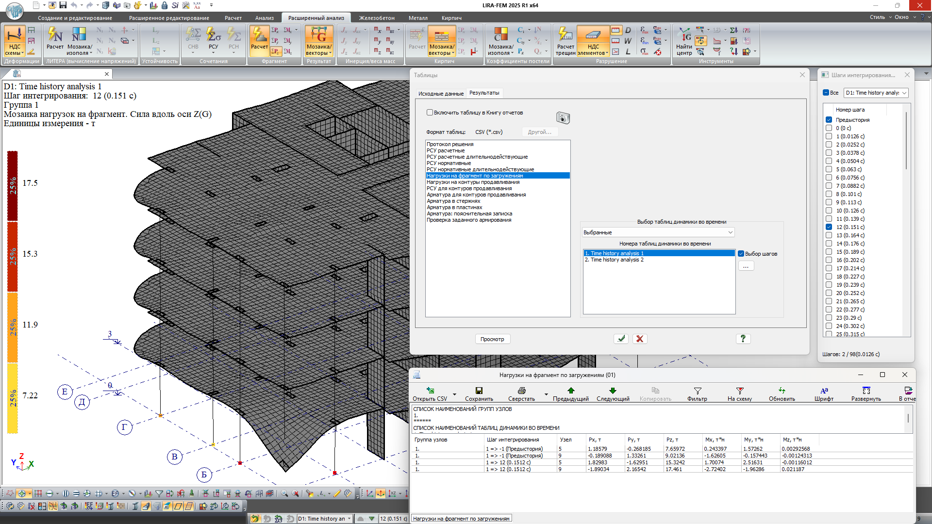
- The option to use an extreme force filter has been added for cases when a structural element consists of a single finite element.
- On the Errors and Warnings tab of the results tables for analysis of steel structures, a separate column has been added listing the element numbers.
- In LIRA-FEM 2025, support for Interactive Tables, the BRIDGE system tables, and the Report (old format) has been discontinued. In the current version, these commands have been removed from the ribbon interface, although they can still be launched via the WINDOW menu.
Cross-Section Design Toolkit
- Added the option to assign linear heat‐technical characteristics to materials, with their subsequent export to the 15th model type.
- Calculation of the sectional moment of resistance of the cross-section has been added to the characteristics table.
Analysis & design of steel structures
- To control the input data and results of the analysis of steel sections in accordance with the DBN V.2.6-:198:2014 standards, mosaic plots of cross-sectional classes have been implemented. The input data and analysis results tables have been expanded.
- A filter of steel tables by the formed groups has been added. After its application, only the steel tables from the selected groups will be displayed in the parameter assignment lists for metal sections or in the list of the Editable Steel Table system.
RC Expert
-
For the DBN V.2.6-98:2009 and EN 1992-1-1:2004/A1:2014 standards, a verification of wall and slab elements has been implemented based on the strength of normal cross-sections and crack resistance.
Analysis & design of reinforced concrete (RC) structures
- For the DBN V.2.6-98:2009 standards, the option to output the safety factor for the specified reinforcement as an envelope result for each check has been added.
- For the DBN V.2.6-98:2009 standards, the option to determine the strength safety factor for precise reinforcement pattern in PR types has been added.
Soil
-
New options for generating Equivalent Foundations for piles have been implemented: when calculating Req using the formula h*tg(θII/4), where h is the depth of pile penetration into the soil, the effect of the depth hd—at which the load-bearing capacity fi of the pile’s lateral surface is not taken into account—has been added. Moreover, if the parameter “h-hd” results in a value of Req less than 0.5D (half the pile’s diameter), then Req is set to 0.5D.
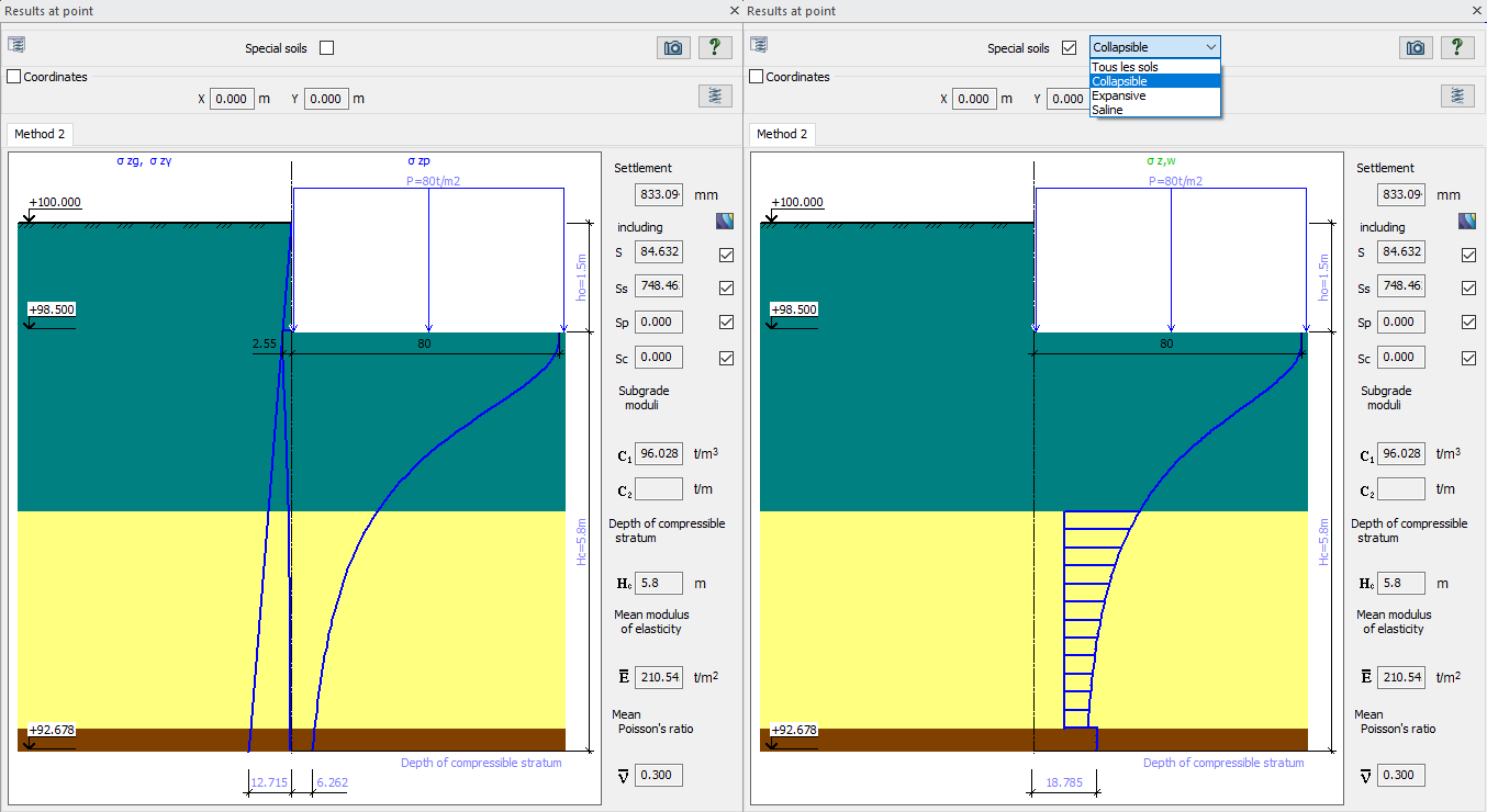
- In the "Results at a Point" dialog box, an option has been added to display calculation results for specific soils. This visualization allows for examining calculation details, serving as a partial trace of the computation. For example, for settlement soils, a hatched area of the full stress diagram Sz is shown, which contributed to the settlement calculation due to consolidation – clearly showing the initial settlement pressure and the extent to which the total stress Sz exceeds the initial settlement pressure layer by layer. Keep in mind that the total stress Sz includes the weight of the settlement soil with the buoyant effect of water taken into account, although in the original calculation without settlement the soil was treated as undrained (waterlogged). Thus, on the new diagram for calculating the specific soil under the foundation of the settlement layer, a jump in stresses is visible that is absent in the calculation without settlement.
- In the scale settings, an option has been added to display percentages in the scale ranges – indicating what fraction of the original data points and computation results fall within the given range.
- In the legend (textual accompaniment) for the calculation results (settlement and subgrade coefficients), the average value calculated from all load contours is now displayed.
Enhancements to Analysis Capabilities
-
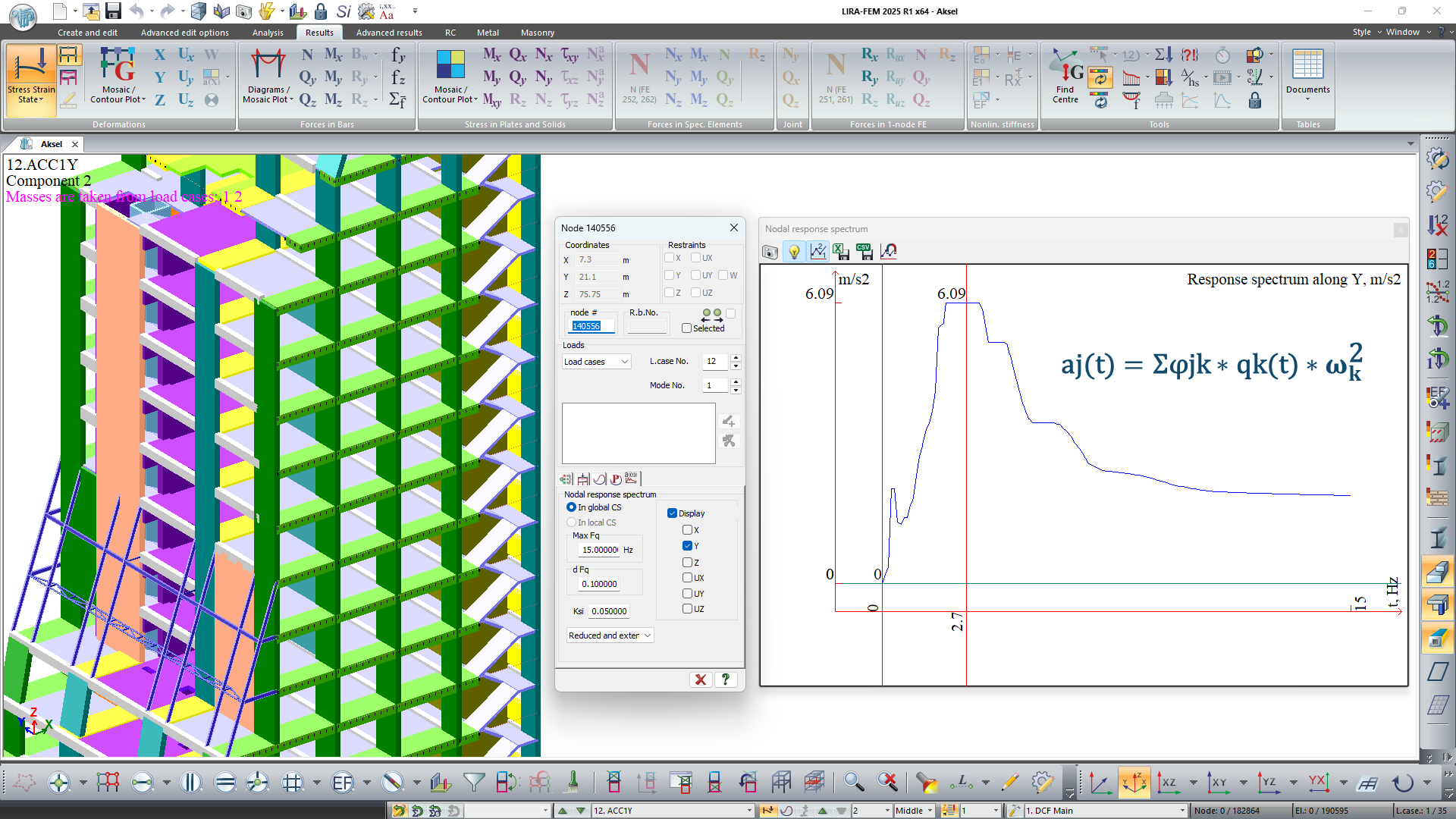
When generating response spectrum graphs using module 27, the approach for determining the final accelerations—taking into account all mode shapes on which the spectrum is based—has been adjusted.
Now the spectrum is generated based on the graph of pseudo-acceleration changes (floor accelerogram), where the acceleration at each moment is determined as follows:
aj(t) = ΣΔjk * qk(t) * ωk²,
where aj(t) is the acceleration of the j-th degree of freedom at time t,
Δjk is the ordinate of the j-th degree of freedom for the k-th mode,
qk(t) is the generalized coordinate for the k-th vibration mode at time t,
ωk is the circular frequency for the k-th vibration mode.This approach produces results analogous to those obtained by direct integration of the equations of motion in geometric coordinates.
-
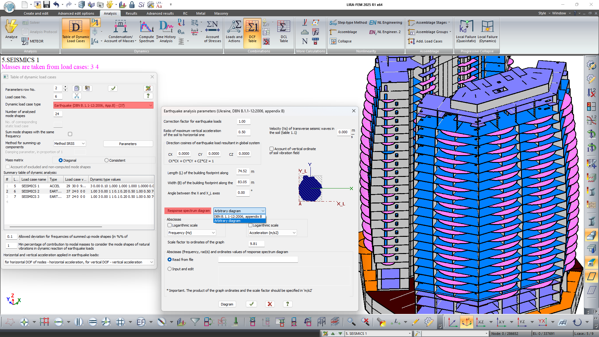
In the new version of dynamic module 37 (DBN V.1.1-12:2006, Appendix V), the option to use an arbitrary response spectrum graph in analyses has been introduced.
Dynamic module 37 allows one to account for the non-uniformity of the ground vibration field in analysis on earthquake loads. This model of earthquake analysis makes it possible to account for the spatial characteristics of structures with irregular layouts according to the propagation scheme of the seismic wave.
This model assumes that the plan of the structure is inscribed in a rectangular area of length L and width B. The propagating seismic wave moves along the long side, causing translational, rotational, and bending vibrations of the structure.
The effect of the seismic wave on the inertial seismic force magnitudes is taken into account using the ordinates of the ground vibration field fk1, fk2, fk3, which are introduced into the formula for the distribution coefficient ηki.
-
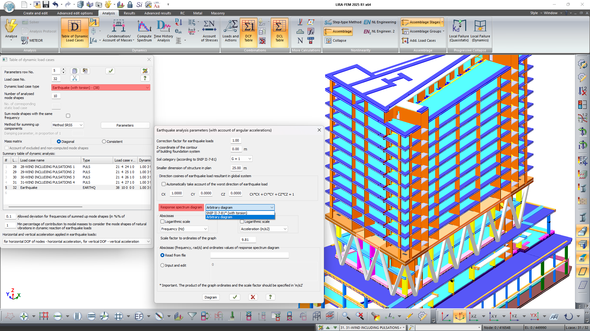
In module 38 (SNIP II-7-81 as amended on 01.01.2000 with torsion considerations), the option to use an arbitrary response spectrum graph in calculations has been added. The integrated model for analysis on earthquake load accounts for the movement of the ground mass under the structure as a single unit. This movement is determined by the vector of translational acceleration and the vector of angular acceleration of rotation.
It is assumed that these vectors are random both in time and space and are defined by the respective parameters. If the cosines for the translational impact vector are specified, then the direction of the angular acceleration vector is automatically calculated as orthogonal to the translational vector. The distribution coefficient in the calculation allows for obtaining inertial seismic forces not only for translational but also for torsional mode shapes.
-
The algorithm for the automatic selection of the step for geometrically nonlinear problems has been modernized.
-
An option has been added for the response spectrum graphs to set the output format of the abscissa values as oscillation frequency or period.
-
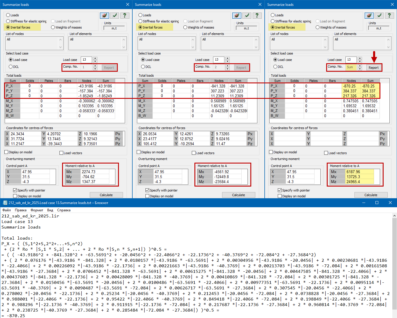
In the analysis results, on the "Summarize loads" menu, functionality has been added to determine the total shear forces and overturning moment from dynamic loads (earthquake and pulsation) for shear and overturning calculations. The summation is performed using the same method (SSRS, CQC, 10%) selected in the dynamic action parameters. A detailed report can be generated based on the summation results for verification and/or documentation purposes.
Tools for evaluation of object properties and analysis results
- New mosaic plots have been implemented:
- Mosaic plots of effective lengths of reinforced concrete bars and plates (walls) relative to the local axes Z1 and Y1;
- Mosaic plots of cross-sectional classes for checking and selecting transverse steel sections for DBN V.2.6-198:2014 "Steel Structures".
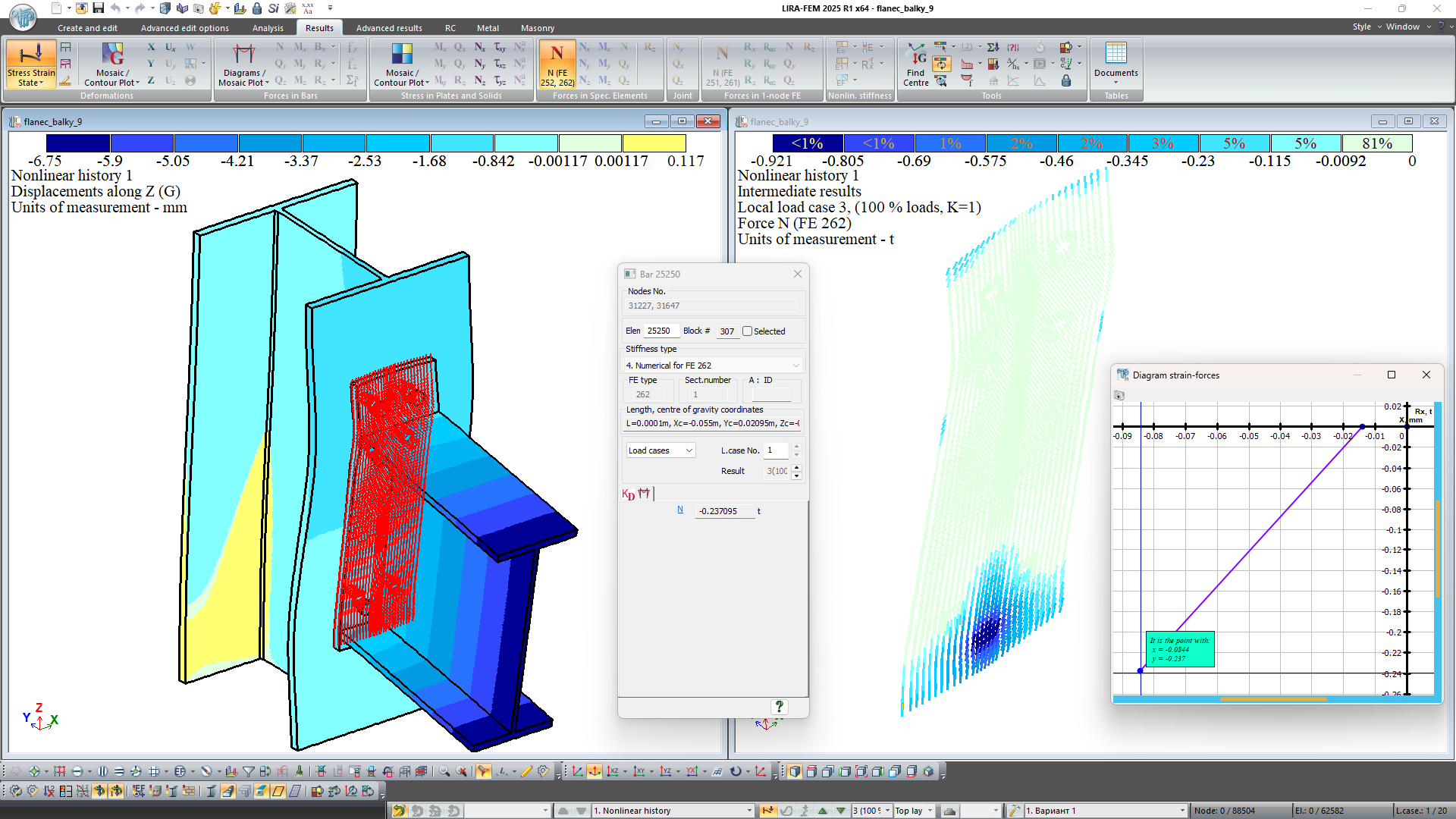
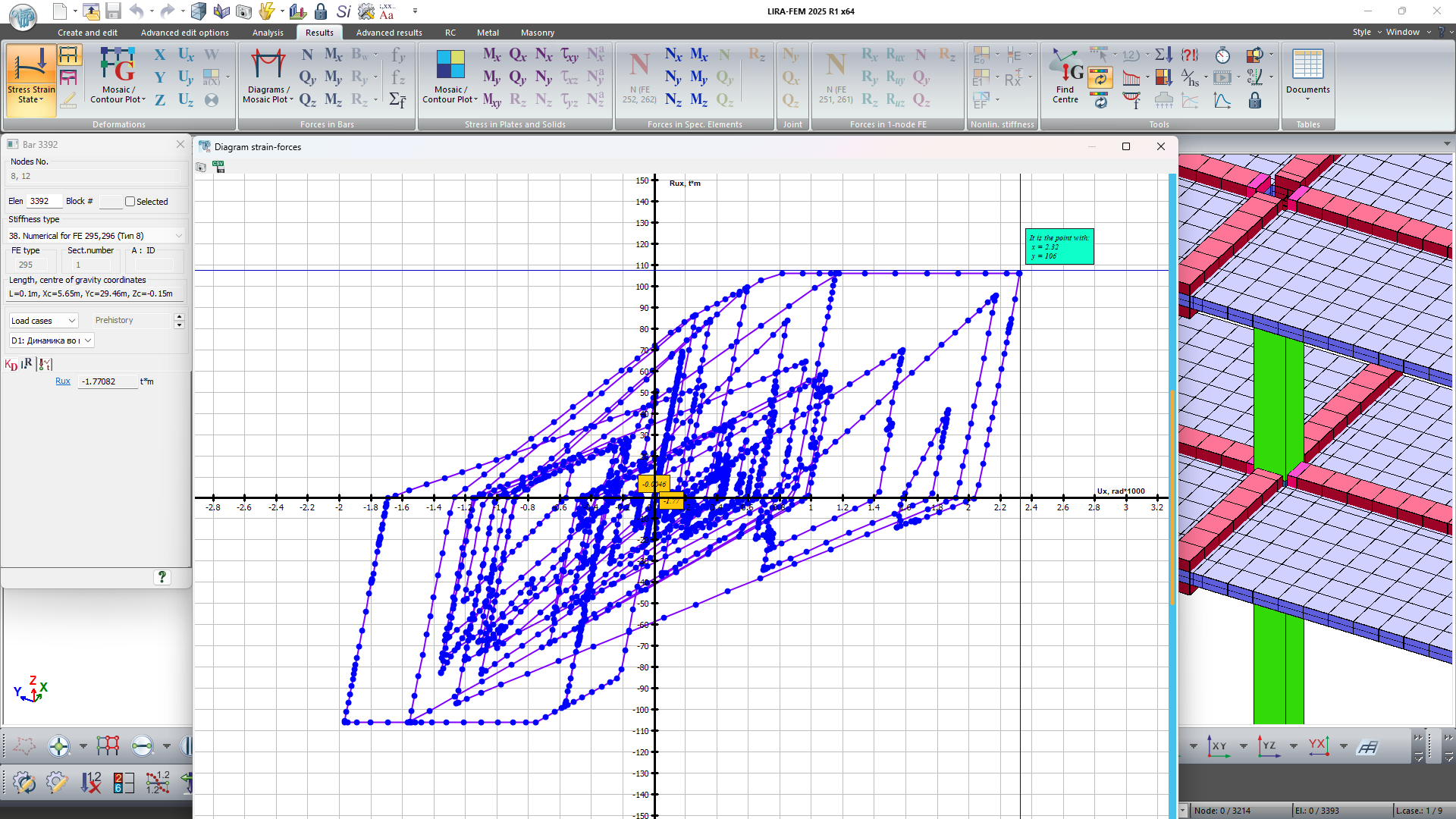
- Graphs can now be plotted for two-node and one-node special elements (FE of elastic springs: 51, 55, 56; 1-node FE of one-way spring with account of ultimate force: 251, 252, 255, 256; 1-node FE of one-way elastic spring with a gap between the structure and the spring: 261, 262, 265, 266; 1-node one-way FE of friction with a gap and accounting for friction between the structure and the spring: 263, 264).
-
It is now possible to save the "strain-force" diagrams for the special FEs in CSV format.
- A new cross-section type "Round Tube" has been added for specifying aluminum sections of bars using the aluminum database.
Generating and modifying the design model
- New types of loads:
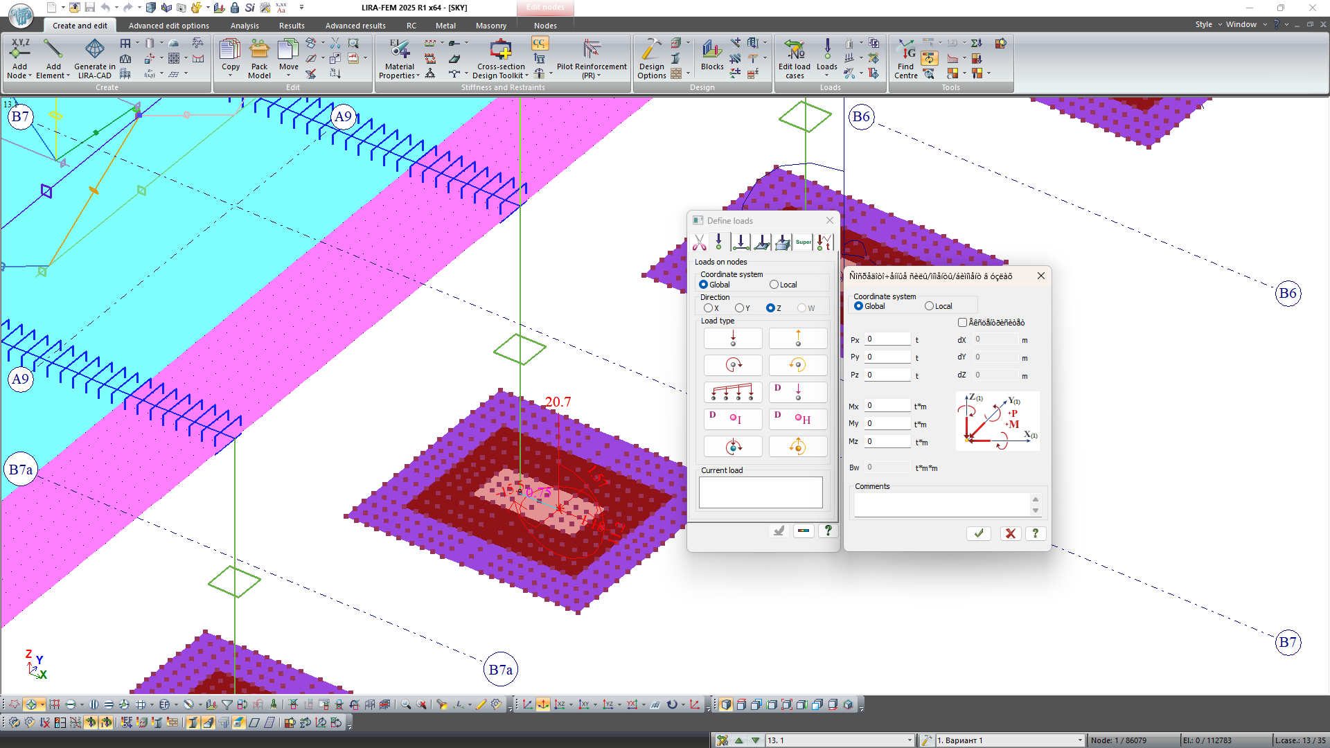
- A unified dialog box for setting, adjusting, or viewing the concentrated loads and moments along the direction of global or local axes, as well as the concentrated bimoment at the nodes. The combined load can be specified in two ways: by applying concentrated loads and moments directly to the node or by applying loads eccentricity relative to the node. Regardless of the chosen method, the combined load is always represented on the model as loads and moments.
- A unified dialog box for setting, adjusting, or viewing the specified translations and rotations along the local axes, as well as the specified warping at the nodes.
- Trapezoidal surface load for plates and solids.
- Trapezoidal load along the line (for bars).
- In the dialog box Surface load (load along the line and across the surface for plates and solids), a search parameter R has been added to configure the search area of finite elements for applying the surface load. It is used when adjusting load contours via input tables.
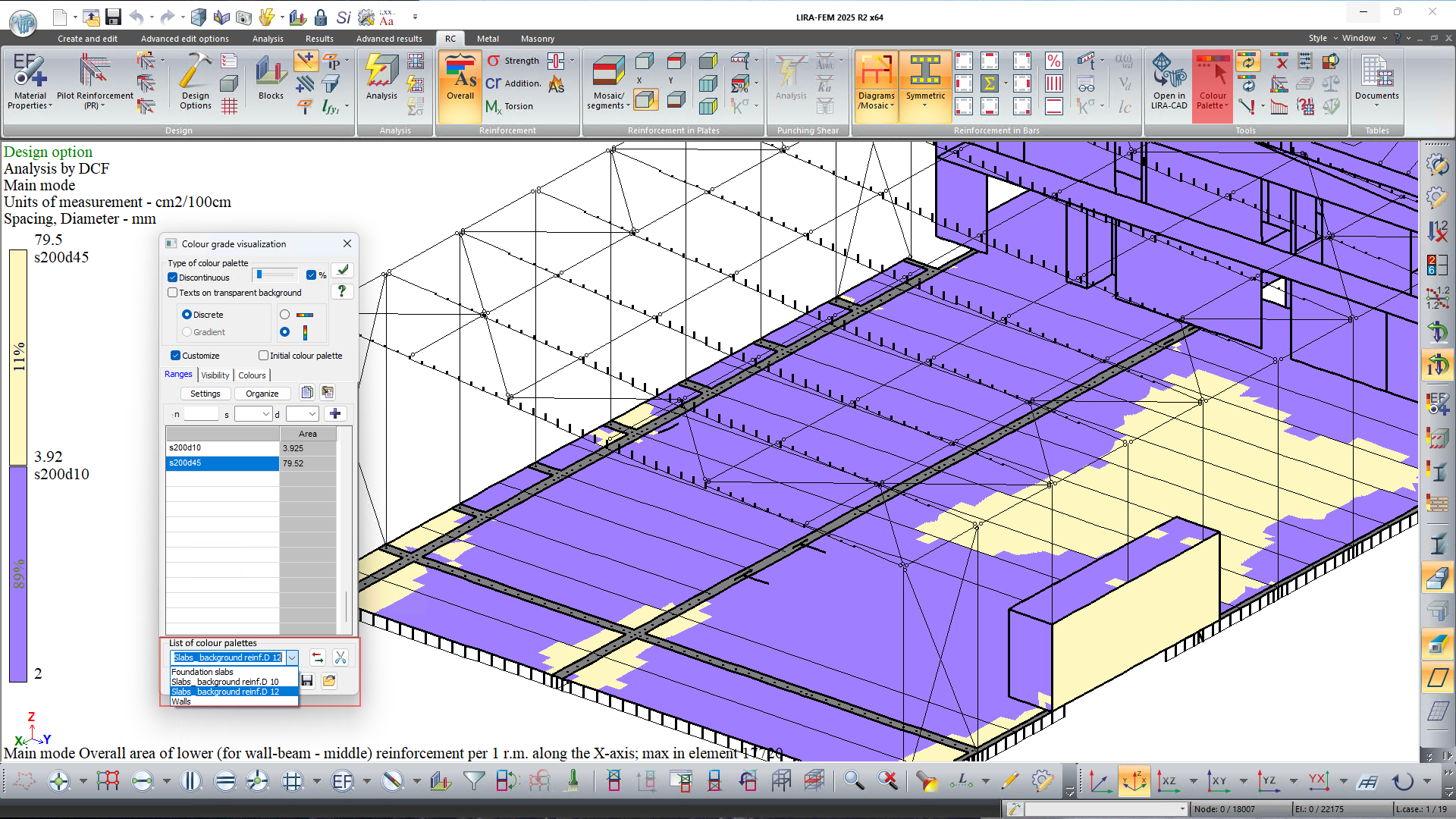
- The option to define sets of configured parameters for reinforcement colour palettes has been added.
- The option to replace one of the three material properties for reinforced concrete, steel, and aluminum/masonry reinforced structures has been added.
- A graphical visualization and documentation of the area of the selected longitudinal reinforcement at the section edges, as well as the area of transverse reinforcement for the specified plate in the current design option, has been implemented.

- The options to change the scaling of loads, the position of circles with tags of grid lines, force diagrams, and reinforcement for bars, mosaic plots for bars and nodes has been added via mouse wheel rotation while holding the Shift key. To revert to the default scaling factor, double-click the mouse wheel while holding the Shift key.
- A new cross-section type "Round Tube" has been added for specifying aluminum sections of bars using the aluminum database.
Generating and modifying the model
- New types of loads have been added:
- Warping at nodes accounts for the inadequacy of the cross-sectional plane of a bar; it is important when for analysis of the thin-walled structures.
- Bimoment at nodes takes into account the moment arising from a force distributed along the height of the cross-section.
- Bimoment by line is mentioned to model a distributed bimoment along an element of the structure.
- Dynamic modules have been added: (22) Impact, (23) Impulse, and (50) Earthquake (AzDTN 2.3-1-2010, modif. on Jan 01, 2014).
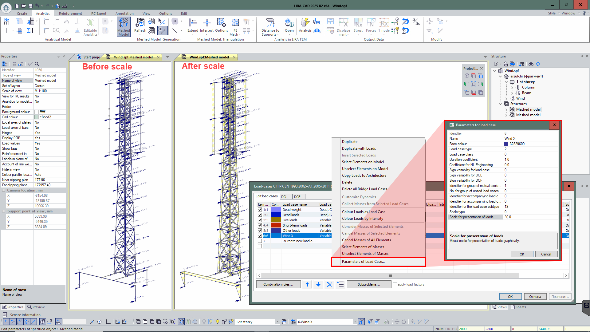
- In the "Parameters for load case" dialog box, the "Scale for presentation of loads" parameter has been added for the selected load. So, it is possible to change the scale of concentrated, linear loads and surface loads, ensuring a more illustrative visualization.
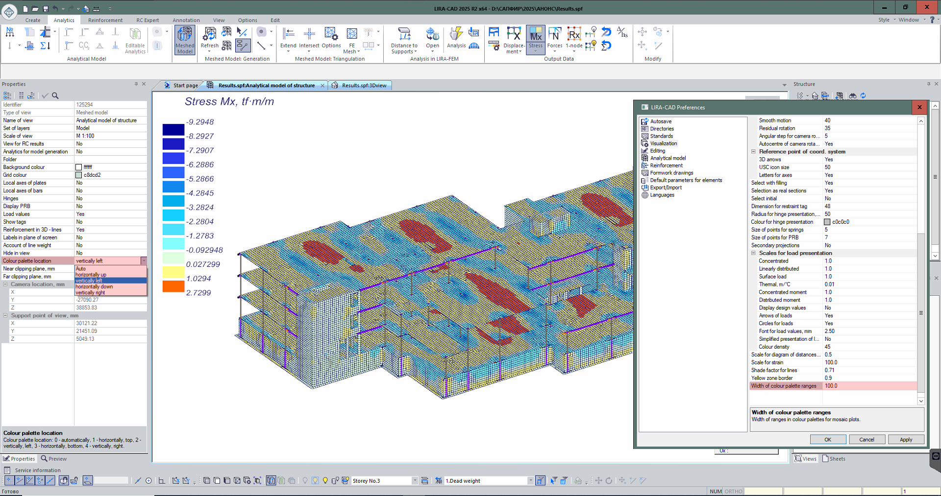
- Location of the colour palette for visualization of analysis results can be customized (in the LIRA-CAD meshed model), including for the visualization of analysis results in the "RC expert" module.
- An option for loads on the staircase has been implemented: to indicate whether the load is included in the additional load case during assemblage.
Components of BIM technology
- New input tables have been added for setting/correcting data: dissipation coefficients, Rayleigh coefficients, an enhancing coefficient Fvk, and custom mosaic data.
- The creation of a single block of axes at the project level—with alignment to selected building floors—has been added, replacing the axes block on every floor as in previous program versions.
- Import of the IFC model into the configured project template has been implemented.
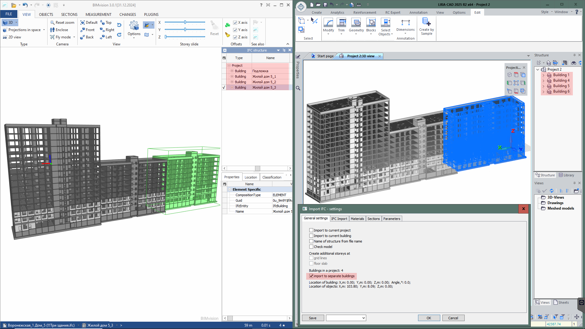
- When importing multiple buildings from IFC, the option to import them into separate buildings in LIRA-CAD has been added.
- The ability to import DWG floor plans into the current or a new project has been added.
- Automatic creation of openings along curved walls based on the DXF/DWG base for floor plans has been added.
- Display of the selected layer (instead of the List input name) in the “Layer Filter” node has been added.
- Improved recognition of the thickness of curved walls when constructing walls along the contour from the DXF/DWG base.
- Creation of openings along curved walls using the “Create windows at the intersection of walls and lines” node with the DXF/DWG base has been added.
- For the node “Advanced floor creation based on specified levels,” an option has been added to enable floor creation as in previous program versions (option “Upper floor levels – Yes”).
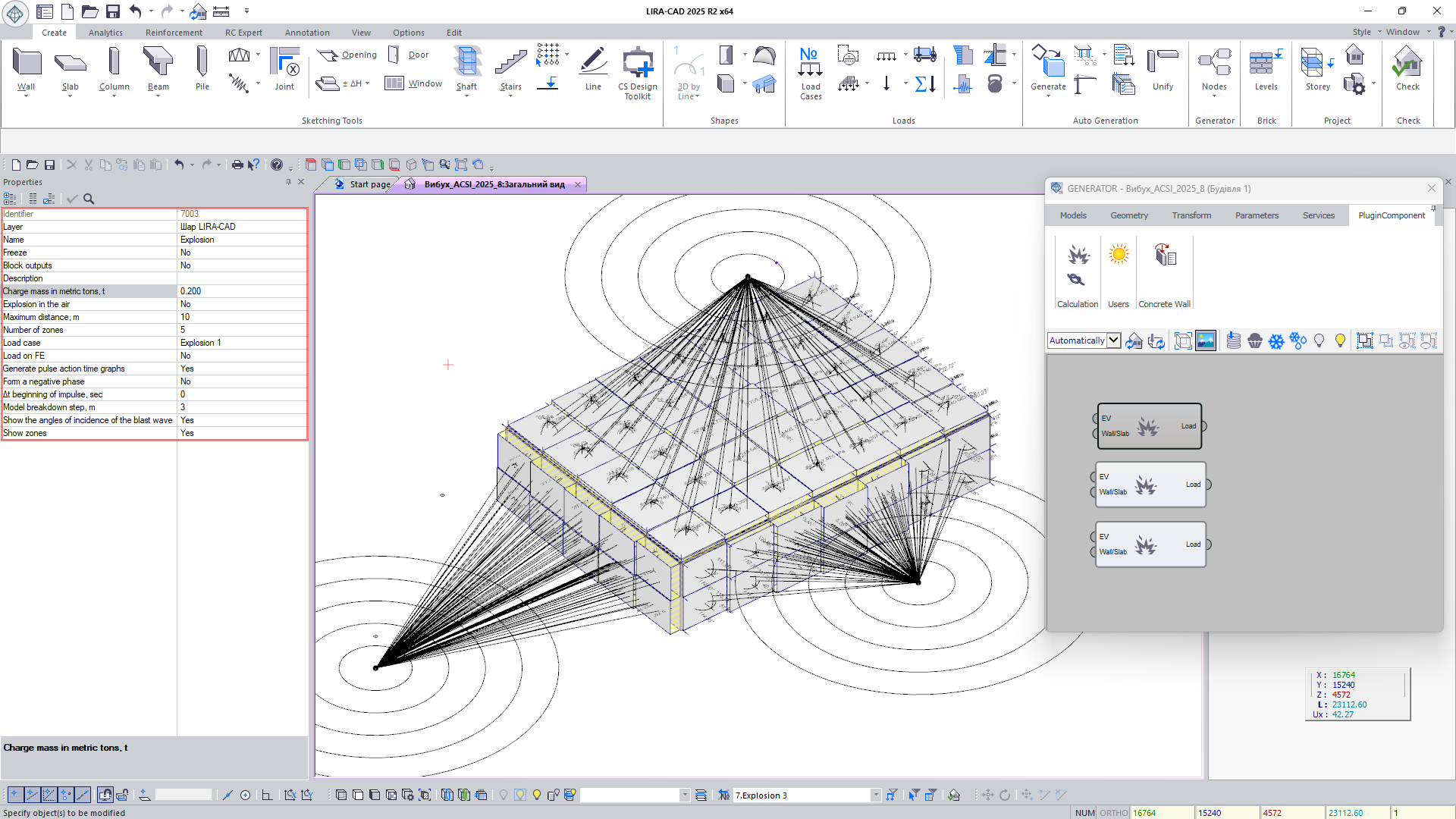
- Expanded functionality of the Blast node: an option has been added to account for or exclude the formation of a negative blast phase when constructing the graph of the explosive wave impulse’s effect (see blast analysis); for rear walls (those positioned at angles greater than 160° relative to the explosion epicenter), the gradual pressure increase caused by the shock wave’s flow along their back surface is taken into account.
Further improvements related to the generation and modification of design model
New option to select the unloading method for each given piecewise linear material stress-strain diagram (14). This parameter is used for iterative physically nonlinear FE when modelling the process of material unloading with account of its nonlinear properties.
New commands that allow the user to create plates on the free faces of selected solids and on the surface of solids by the specified plane and angle of deviation. Such options will be helpful, for example, when creating target plates of plate analogue; elements of convective heat transfer on faces of solids of heat conductivity; when modelling 3D unlimited soil body, etc.
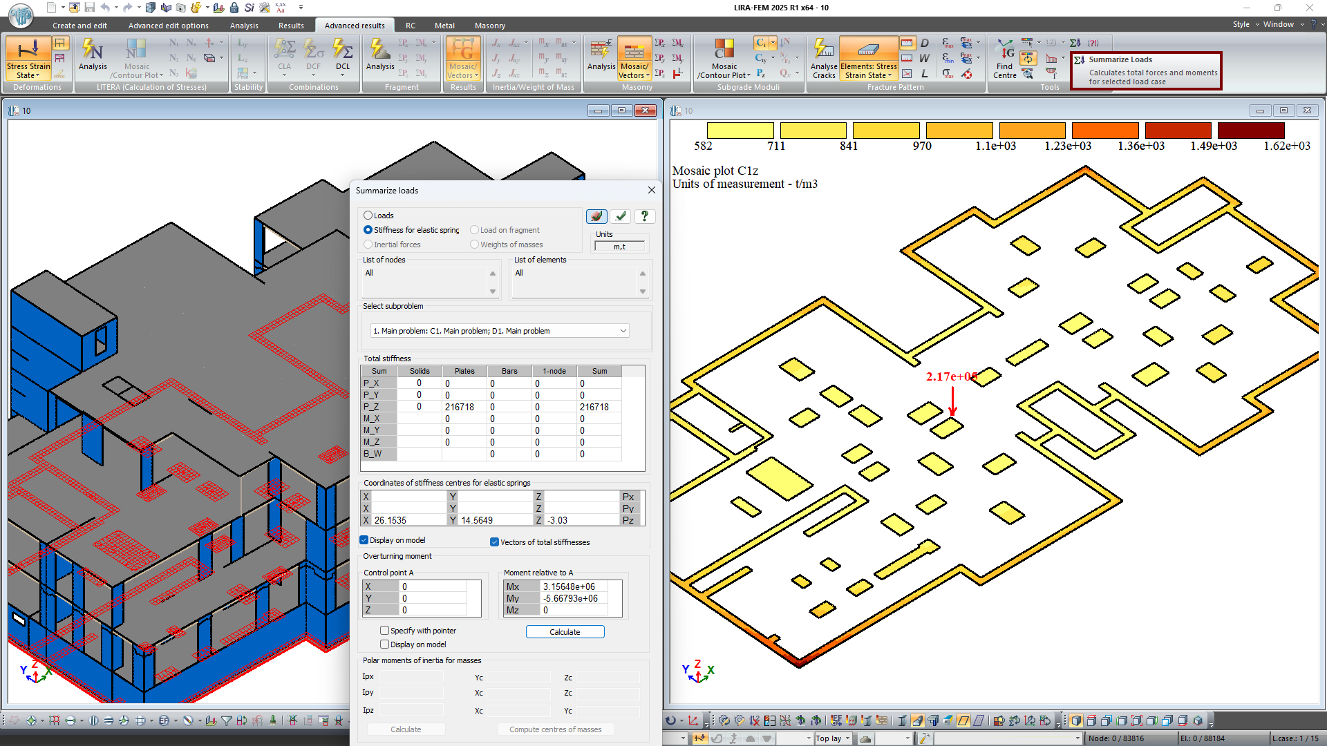
For plates and bars on an elastic foundation, the calculation of the total stiffness of the restraints along the Z-axis by C1z data is implemented (the initial specified stiffness may change after recalculation of the elastic foundation of the model attached to the soil model).
For 1-node elements FE 51, FE 56, FE 57, that model elastic foundations or piles, the specified or recalculated stiffness Rx, Ry, Rz is considered when calculating the total stiffness of restraints along the X, Y, Z axes.
Note. When the stiffnesses of restraints are summed up, appropriate sets of subgrade moduli C1z (property set C) and sets of coefficients to the modulus of elasticity kE (property set D) are considered according to the selected subproblem. The stiffnesses of the 1-node elements FE 51, FE 56, FE 57 are summed up with account of the corresponding kE coefficients.
New options to display on the model the following data:
- comments on the assigned stiffnesses;
- contours for uniformly distributed load for plates and solids;
- overturning moments relative to a specified point;
- numbers of assemblage groups;
- change in the size of the colour zone when generating mosaic plots of properties and results at nodes;
- directions of the principal axes of the bars calculated as a result of physically nonlinear analyses.
In the dialog box for creating design options, there is a new command that allows you to create a new design option for the model based on the template of the selected design option.
New command to display in a new window the nodes and elements previously selected on the model.
Now it is possible to copy and add (from the Clipboard to the current problem) materials for masonry reinforced structures for all building codes and design options.
When design model is automatically divided into structural blocks Plate, Wall, there is a new option to consider gaps in their contours (if there is no common nodes) in one plane. This option also affects the generation of a regular Block.
New option to automatically generate structural blocks (column, beam, slabs) when creating a 3D frame. It is also possible to automatically generate grid lines and elevations.
Import of arc grid lines from the LIRA-CAD module is supported now. The arc grid lines can be edited using the following tools: rename, define Z-axis snap, and delete. It is possible to check the presentation and parameters for selection of nodes and elements when clicking on the tag of the arc grid line or when selecting several grid lines with the rectangular 'selection window'.
New command to delete all grid lines and height elevation on the model.
New option to rename height elevation to the existing functionality for renaming grid lines.
When you add bar elements and divide bars into several parts, there are commands that allow you to unite new elements into a structural block and structural element.
To check the input data of structural elements, there is a column with the total length of the bars included in the structural elements.
When selected bars are united into one, there are options that enable you to check the coincidence of StE types, the offsets, restraints and PRBs. If the corresponding checkboxes are selected, the chain of selected bars will be united only in the regions where the corresponding parameters of bar coincide or in regions between nodes with restraints or PRBs.
For more convenient visualisation of the plates, a projection on the XOY-plane (top view) is added; the Y-axis is horizontal here.
New option to sort by parameters in the dialog box for perfectly rigid bodies.
Now it is possible to place a rectangular grid in all four quadrants of the plane relative to the centre of the grid.
Modelling the construction process
Assemblage stages may be generated automatically based on height elevations. With this option, assemblage stages are created, and lists of assembled elements (that are located between neighbouring elevations and/or at the level of the lower/upper elevation) are generated automatically.

For problems in which erection process is modelled, now there is an option to organize the list of load cases. It is now possible to move load cases up or down in the list, and to insert a new load case above existing load cases in the list.
Additionally, the assemblage stages can be moved up or down. In this case, the following data is automatically transferred: the numbers of assembled or disassembled elements, the parameters and coefficients that influence the concrete's strength and modulus of deformation, and the coefficients that account for extra load cases during the assemblage stage. There is no change in the order of load cases.
Time history analysis
The new option to define the dynamic uniformly distributed load on bars and plates for time history analysis. The following diagrams for such loads are implemented: piecewise linear load (broken) with arbitrary step; sinusoidal load; piecewise linear load (broken) with uniform step.
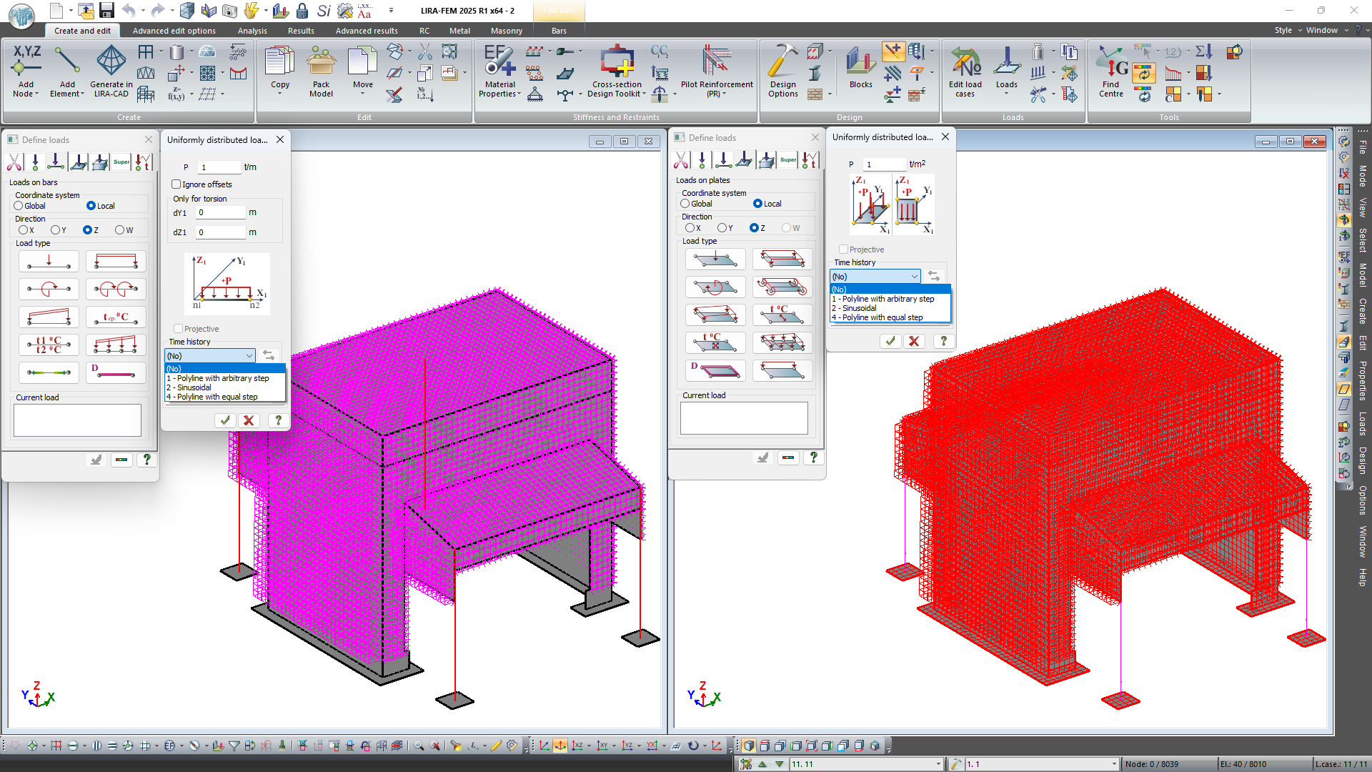
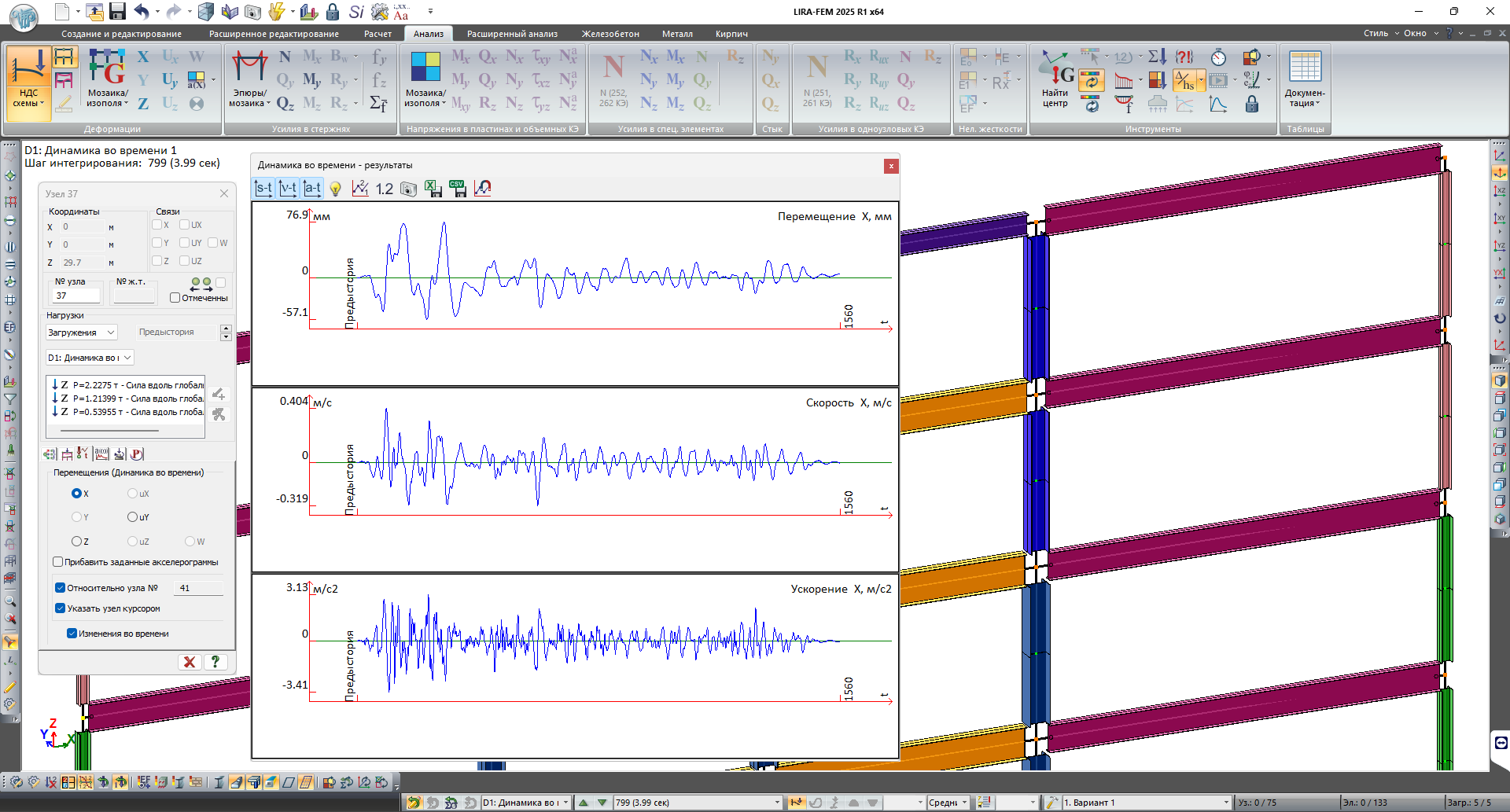
Now it is possible to carry out analyses using the direct dynamic method (Time History Analysis system) for several dynamic load cases within one design model. Moreover, an algorithm has been implemented to remove restrictions on the number of integration steps. It enables the user to evaluate different scenarios of dynamic load and carry out analyses with higher accuracy, which is especially important for analyses of buildings and structures on earthquake loads, air shock wave effects, etc.

The user could also carry out an analysis on progressive collapse within a single design model for several scenarios of local failures in elements of structure. The analyses are carried out by the dynamic method of direct integration of the equations of motion in time (Time History Analysis system) in linear and nonlinear statement. This method allows the user to take into account damping effects.

New option to calculate the temperature field for problems with transient heat transfer analysis for several scenarios of time-varying temperature within a single design model.
New option to determine mass (α) and stiffness (β) proportionality constants to account for Rayleigh damping by specifying frequencies and damping coefficients.
Equivalent cross section
In analysis of reinforcement and/or analysis of pilot reinforcement in RC and composite (RC & steel) elements, selection and check of cross-sections of steel elements, the building codes are oriented towards standard types of cross-sections. For an arbitrary cross-section, it is only possible to obtain a picture of the stress-strain state.
New system to create an equivalent cross-section (beam, T-section with a flange at the top or bottom, I-section, box, cross, or channel) from an arbitrary cross-section based on geometric properties. A file created in the Cross-section Design Toolkit module defines the initial cross-section.
The following characteristics are approximated for a specified section: area, principal moments of inertia and section modulus. The user-defined values of weight coefficients are taken into account (by default, all weights are equal to 1).
An equivalent cross-section is an abstract description of stiffness; it approximates the behaviour of a structure or element under load. Such a cross-section has the same geometric and mechanical properties that allow to adequately describe the behaviour of a structure or element under different loading conditions.

Orthotropy of shape
A new tool Orthotropy of shape is mentioned to determine and the elastic properties for structurally orthotropic plates of various configurations. The functionality covers a wide range of slab types including:
- slabs with single- and double-sided unidirectional ribs;
- slabs with single-sided bi-directional ribs;
- unidirectional and bi-directional box-shaped slabs;
- beam system;
- corrugated plate (trapezoidal or wavy);
- slab on corrugated plate taking into account the steel material;
- hollow slab (with round or oval holes).
Structural orthotropy is used in finite element design models in order to more correctly represent the behaviour of real structures while accounting for their anisotropic features. This is especially important for the design of bridges, metal structures, and other complex engineering objects where optimisation of stiffness and strength is required.

Other features analysis results
In the "State of the section" window for physically nonlinear iterated plates, it is possible to display stress and strain diagrams with indicated values for each elementary strip of the section.
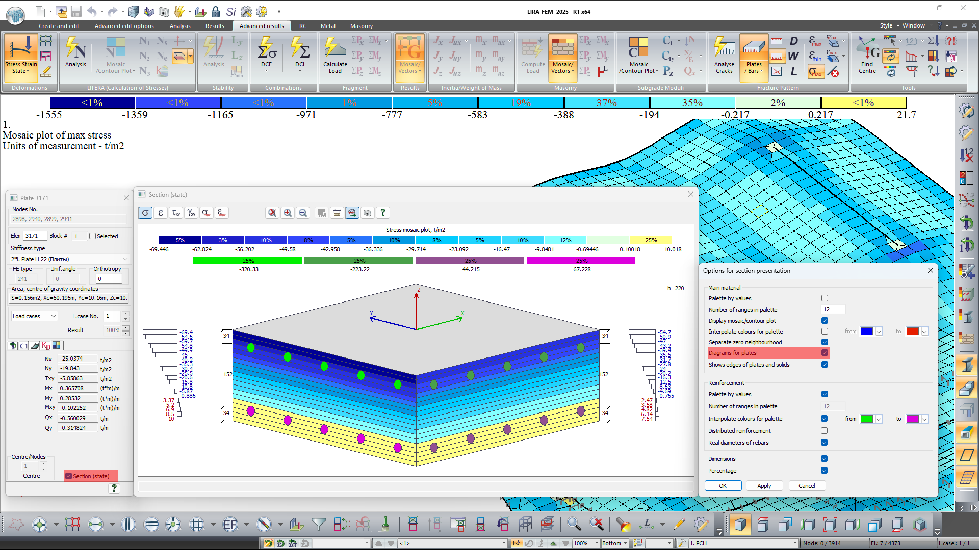
New mosaic plots are implemented:
- Group of mosaic plots of total stiffnesses Rx, Ry, Rz in pile caps.
- Mosaic plot of the stability analysis results for the universal bar in metal elements, % of load-bearing capacity for Eurocode 3 EN 1993-1-1:2005/AC:2009, SP RK EN 1993-1-2:2005/2011.
- A group of mosaic plots for evaluating the input data of the problems in which the erection process was modelled (mosaic plots of assembled and disassembled elements at each assemblage stage, mosaic plot for No. of assemblage groups of elements, mosaic plot of correction factors to the modulus of elasticity and to the concrete strength at each assemblage stage for each group of elements).
- A group of mosaic plots for angles between the local axis of nodes and the global axis along selected directions.
- Mosaic plot for numbers of the specified groups of loads on fragment (the groups that contain the node).
- Mosaic plots for element sensitivity parameters to buckling.
- Mosaic plot for the direction of displacement in mass application.
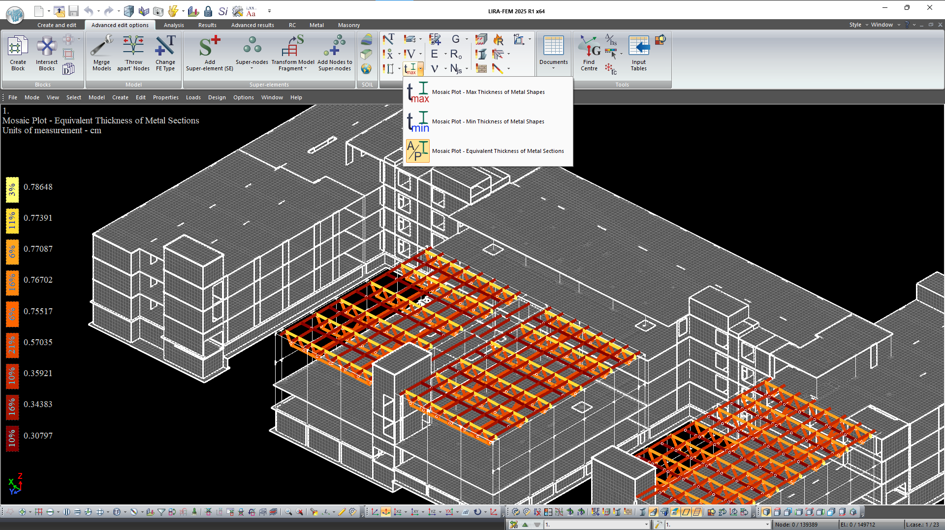
- Mosaic plot for selected cross-sections of metal structures.
- Mosaic plot for the reduced thickness of metal sections (ratio of the cross-sectional area to the length of the perimeter of the section).
The Diagram for floor slab stiffness is generated for floor slabs both from plates and bars. The diagram is designed to classify the stiffness of the slab disc in its plane, %, according to paragraph 2.2.2.5.4 (f-la. 2.2 and 2.4) of NTP RK 08-01.2-2021 (to SP RK EN 1998-1:2004/2012) "Design of earthquake-resistant buildings".
The scale settings now contain an option that allows you to place scale labels on a transparent background.
In modes of displacement contour plots for bars, it is possible to present displacements at nodes.
To generate the graph of nodal displacements in the time history analysis, the user could define the number of nodes relative to which the displacements are recalculated.
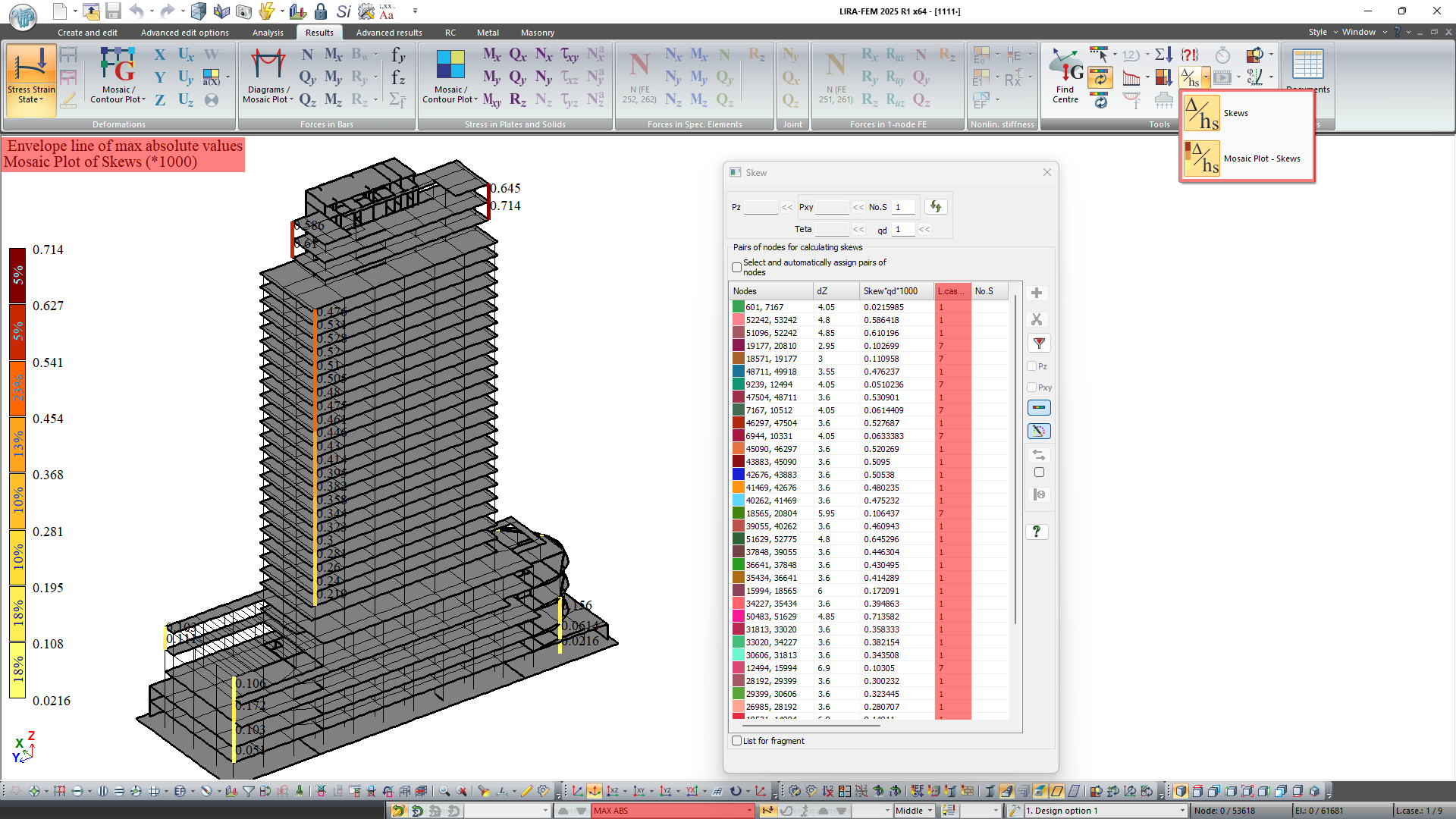
The envelope diagrams (by max, min and absolute values for load cases and DCL) may be generated for structural skews and displacement diagrams (Fz, Fy) of bars.
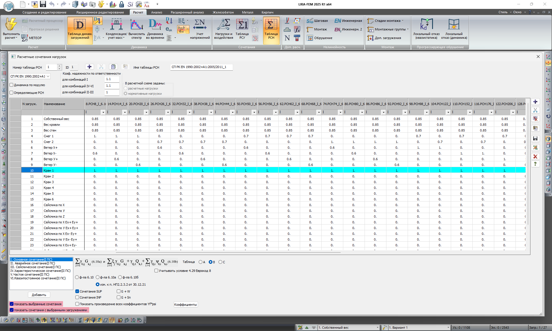
New filters are added to the DCL table to define and check the input data; they enable the user to quickly find the necessary combinations by type and content of the selected load cases.
Новости 1 - 20 of 49
First | Prev. | 1 2 3 | Next | Last