Eurocode 3. Steel structures
LIRA-FEM* software supports a variety of national building codes, as well as European standards (Eurocodes) and national annexes to Eurocodes for Ukraine, the Republic of Kazakhstan, and the Republic of Belarus.
Eurocode 3. Steel structures
Analysis of steel structures according to Eurocode 3 in LIRA-FEM (LIRA-SAPR)
Analysis of steel structures, options to select and check the steel sections according to Eurocode 3 in LIRA-FEM:
- EN 1993-1-1:2005/AC:2009. Eurocode 3: Design of steel structures - Part 1-1: General rules and rules for buildings;
- SP RK EN 1993-1-1:2005/2011. Eurocode 3. Design of steel structures. Part 1-1 -- General rules and regulations for buildings (EN 1993-1-1:2005);
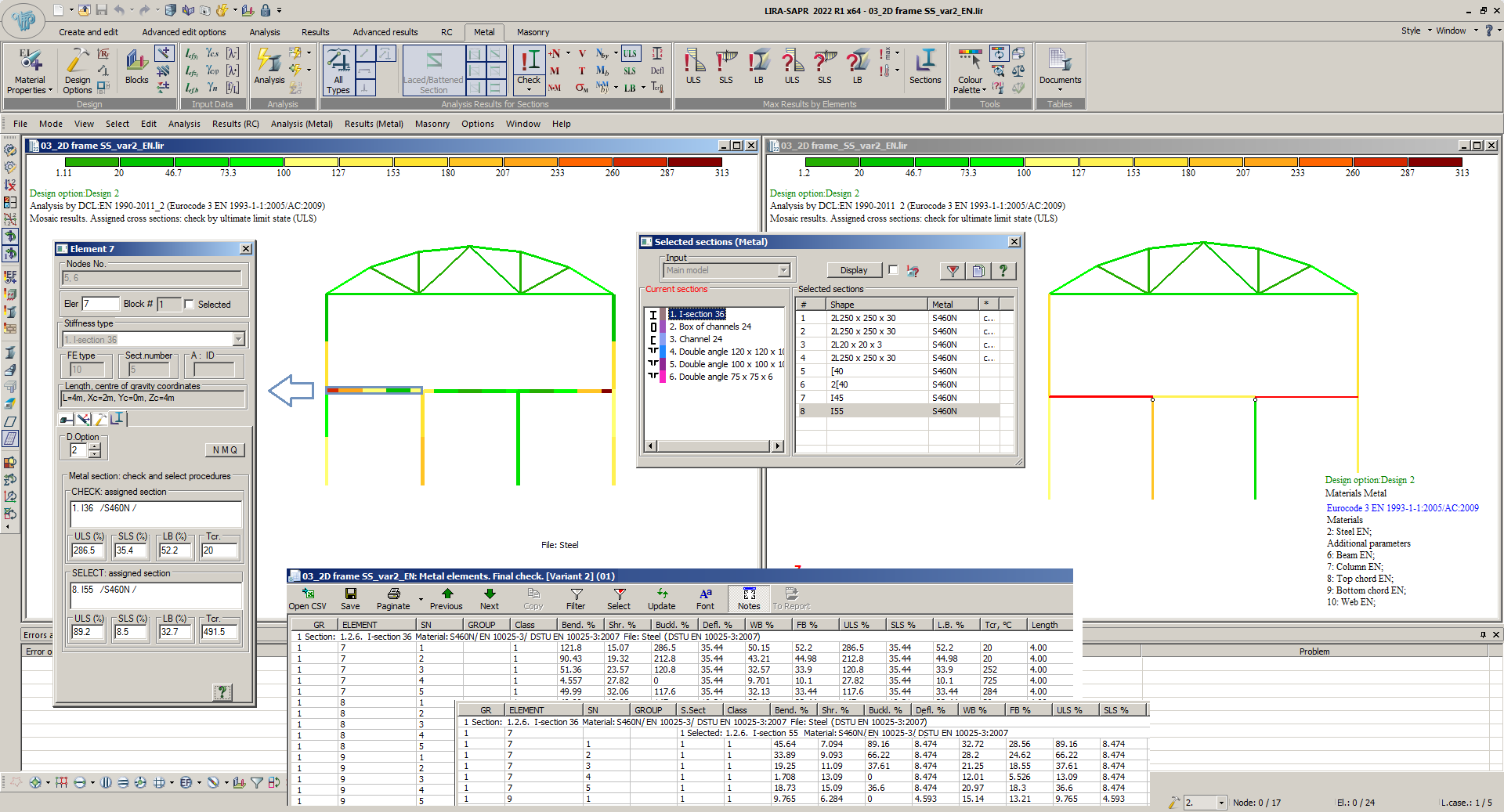
After the check of steel sections, the following results are available: the utilization ratio of the load-bearing capacity obtained from the respective checks by Eurocode 3 are presented as of tables for the different element types (beam, column, truss, universal element), as well as mosaic plots of the values on the design model in sections and for the whole elements. The result of the selection of sections is the search for profiles from certain steel tables under the condition of ensuring bearing capacity and serviceability according to the specified criteria.
Design of steel structures is carried out on the basis of normative data that contain information on design properties of steel, dimensions and geometric properties of produced steel profiles. The SRS module of the program is mentioned to edit the steel tables of rolled and welded sections.
It is allowed to combine several elements of the same type into a structural element.
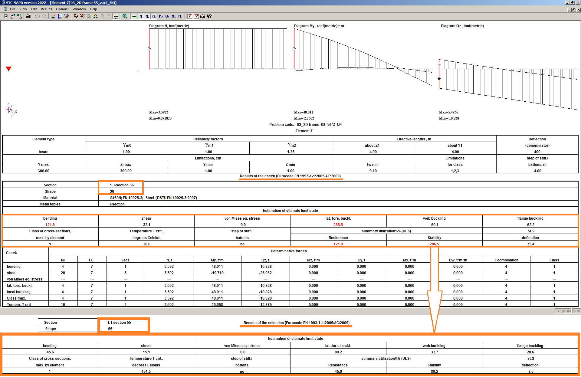
In the STC module for selected elements, after local analysis (check and selection with subsequent check), tables of the input data, characteristic forces and analysis results of all checks are displayed. The information may be displayed both for the whole element and for all its design sections.
Checks of cross-sections in analysis of steel structures according to Eurocode 3
The tables contain lists of checks by ultimate limit state and serviceability limit state for elements of column, beam, truss element types. Universal elements are calculated three times: as a truss, as a column, as a beam. The most unfavourable of the three results is selected.
Checks for columns according to Eurocode 3
|
Check |
Clause in EN 1993-1-1 |
|
Resistance in bending with axial force |
6.2.5, 6.2.8, 6.2.9, 6.2.10 |
|
Resistance in shear |
6.2.6, 6.2.7.9 |
|
Resistance in torsion |
6.2.7 (without bending and torsional moment) |
|
Stability relative to Y1, Z1 |
6.3.1, 6.3.2, 6.3.3, appendix B |
|
Local buckling |
by 5.5.2, 5.6 (table 5.2) |
|
Critical temperature |
EN 1993-1-2:2005 (E) |
Checks for beams according to Eurocode 3
|
Check |
Clause in EN 1993-1-1 |
|
Resistance in bending |
6.2.5, 6.2.8 |
|
Resistance in shear |
6.2.6, 6.2.7.9 |
|
Stresses by Mises |
6.2.1.5 |
|
Resistance in torsion |
6.2.7 (without bending and torsional moment) |
|
Stability of beam |
6.3.2 |
|
Deflection |
7.2.1, 7.2.2 |
|
Local buckling |
by 5.5.2, 5.6 (table 5.2) |
|
Critical temperature |
EN 1993-1-2:2005 (E) |
Checks for trusses according to Eurocode 3
|
Check |
Clause in EN 1993-1-1 |
|
Resistance in tension |
6.2.3 |
|
Resistance in compression |
6.2.4 |
|
Stability relative to Y1, Z1 |
6.3.1 |
|
Local buckling |
by 5.5.2, 5.6 (table 5.2) |
|
Critical temperature |
EN 1993-1-2:2005 (E) |
Classification for sections of steel structures according to Eurocode 3
The classification of cross-sections of steel structures by Eurocode 3 is carried out according to section 5.5.2 of EN 1993-1-1:2005/AC:2009.
Four classes of cross-sections are defined, as follows:
- Class 1 cross-sections are those which can form a plastic hinge with the rotation capacity required from plastic analysis without reduction of the resistance.
- Class 2 cross-sections arc those which can develop their plastic moment resistance, but have limited rotation capacity because of local buckling.
- Class 3 cross-sections are those in which the stress in the extreme compression fibre of the steel member assuming an elastic distribution of stresses can reach the yield strength, but local buckling is liable to prevent development of the plastic moment resistance.
- Class 4 cross-sections are those in which local buckling will occur before the attainment of yield stress in one or more parts of the cross-section.
In Class 4 cross-sections, effective widths may be used to make the necessary allowances for reductions in resistance due to the effects of local buckling, see clause 5.2.2 EN 1993-1-5.
The ultimate width-to-thickness ratio for compression parts is computed according to the formulas presented in table 5.2 of Eurocode 3.
The section class is determined for each combination of forces acting in the section. A cross-section is classified according to the highest (least favourable) class of its compression parts.
It is possible to limit the class of the cross-section that should be selected.
Asymmetric sections (angle, channel, asymmetric I-beam) are calculated only within the elastic stage (class 3). Symmetric sections with no compressed elements are checked for strength using the plastic modulus, i.e. classified as class 1.
Resistance of sections in steel structures according to Eurocode 3
The resistance of steel members is checked according to Eurocode 3 section 6.2 of EN 1993-1-1:2005/AC:2009 and the check procedures are grouped according to the element type:
|
Element type |
Types of force |
Resistance in |
|
Beam |
Bending moments My, Mz, shear forces Qz, Qy, torque Mx, bimoment Mw |
Bending, shear, torsion; Mises' stresses at the critical point |
|
Column |
Axial force N, bending moments My, Mz, shear forces Qz, Qy, torque Mx, bimoment Mw |
Bending with axial force, shear, torsion |
|
Truss |
Axial force N |
Tension, compression |
|
Universal |
Axial force N, bending moments My, Mz, shear forces Qz, Qy, torque Mx, bimoment Mw |
Bending with axial force, shear, torsion; Mises' stresses at the critical point |
The strength of sections in which plastic hinge may be generated (class 1, 2) under the combined action of axial forces and bending moments is checked by formulas of clause 6.2.9.1 (5).
The Mises' stresses for the critical point of the cross-section are computed only in the elastic stage.
The effects of local stresses from transverse load applied to the web (clause 6.2.8 (6)), bending-torsional moment, and shear lag effects are neglected.
Resistance of steel elements in shear and torsion according to Eurocode 3
The resistance of elements of metal structures in shear is checked by Eurocode 3 section 6.2.6 of EN 1993-1-1:2005/AC:2009 and in torsion - by section 6.2.7 of EN 1993-1-1-:2005/AC:2009.
The shear areas and torsional moment of inertia specified in the steel tables are considered in the analysis. If they are not available, they are calculated according to clause 6.2.6 (3) and by approximate formulas, respectively.
In the check for torsion, normal stresses from bimoment and tangential stresses from pure torsion are considered in the analysis. The tangential stresses from bending-torsional moment are neglected in the current version.
A component equal to the ratio of the bimoment to the design resistance of the section in warping (in elastic or plastic stages) is added to the strength design criteria checked in case of bimoment.
When shear force and torsional moment are applied together, the shear strength is reduced from Vpl.Rd to Vpl.T.Rd according to clause 6.2.7 (9).
Buckling resistance of steel elements according to Eurocode 3
The buckling resistance of elements of steel structures is checked by Eurocode 3 section 6.3 of EN 1993-1-1:2005/AC:2009.
Buckling curves for compressed elements of constant cross-section are taken according to table 6.2.
The slenderness for torsional and torsional-flexural buckling is determined according to subsection 6.3.1.4.
The interaction coefficients in the formulas that describe the combined bending and axial compression are found according to Appendix B.
The buckling curve in bending is generally determined according to section 6.3.2.3.
The coefficients C1, C2, and C3 that take into account the boundary conditions and the type of external load on the element are obtained from tables B1 and B2 Design Manual For Structural Stainless Steel - Third Edition, 18 April 2006, Euro Inox and The Steel Construction Institute and table 4.2 NCCI: Mono-symmetrical uniform members under bending and axial compression SN030a-EN-EU. These coefficients are used to compute the critical moment Mcr (by the bending-torsional buckling mode).
To determine the conditional slenderness in the bending-torsional buckling, the elastic critical moment of the total buckling Mcr is calculated. Since Eurocode 3 does not provide any formulas or rules for calculating Mcr, then the critical moment is defined based on the following sources: NMono-symmetrical uniform members under bendiCCI: Elastic critical moment for lateral torsional buckling SN003a-EN-EU and NCCI: Mono-symmetrical uniform members under bending and axial compression SN030a- EN-EU, Design Manual For Structural Stainless Steel - Third Edition, 18 April 2006, Euro Inox and The Steel Construction Institute.
Local buckling of steel elements according to Eurocode 3
The local buckling of sections of elements in steel structures is checked according to Eurocode 3, the ultimate c/t ratios for class 3 are used, they are taken according to table 5.2 of EN 1993-1-1:2005/AC:2009.
Moreover, the local buckling of the web in shear force is checked according to section 5 of EN 1993-1-5.
In the current version, the effect on the local buckling of elements on the local compressive stresses from transverse load (mentioned in sect. 6.2.8 (6)) is neglected.
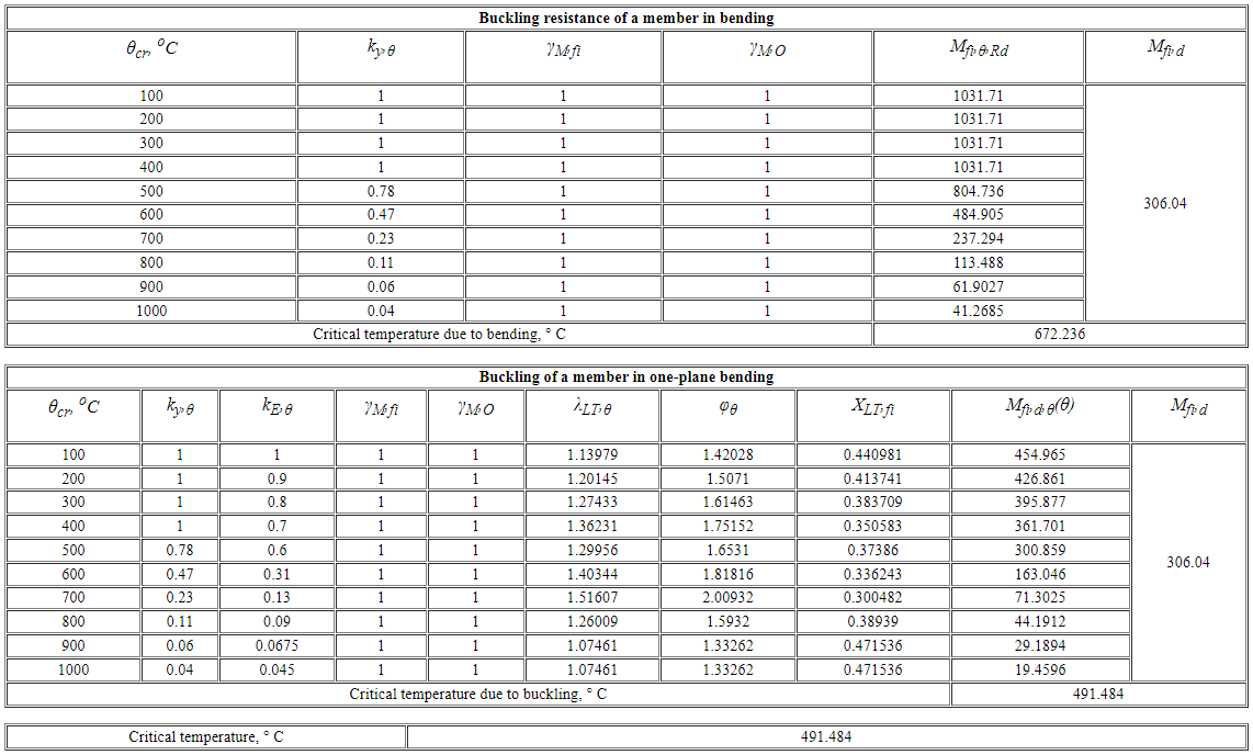
Critical temperature of steel elements according to Eurocode 3
The analysis of critical temperature is carried out according to EN 1993-1-2:2005.
The load-bearing capacity of the element is reduced when the temperature is increased. A comprehensive report on such a reduction is presented in the local mode of analysis of a structural element (STC module).
Peculiarities in analysis of steel structures according to SP RK EN 1993-1-2:2005/2011
Code of Regulations of the Republic of Kazakhstan 'Design of steel structures. Part 1-1: General structural rules' is identical to the European building code 'EN 1993-1-1:2005/2011 Eurocode 3: Design of steel structures. Part 1.1: General rules and rules for buildings' (including all amendments for February 2006 and March 2009) taking into account the 'National Annex to SP RK EN 1993-1-1:2005/2011 Design of steel structures. Part 1-1. General rules and regulations for buildings'. The analysis according to the state regulations of the Republic of Kazakhstan takes into account the provisions of the national annex.
Input parameters for the analysis of steel elements
- Physical and mechanical properties of the material and section profile. The material is selected from the material tables, the profile from the section files. For laced sections, the type of lacing is additionally specified.
- Element type. Each type of element (beam, column, truss, universal) has its own list of necessary parameters that describe peculiarities of structural element behaviour.
- Partial safety factors for strength, stability and at bolted joints: Ym0 - partial safety factor for the strength analysis of cross-sections of classes 1, 2 or 3; Ym1 - partial safety factor for the stability analysis of the bar; Ym2 - partial safety factor for the analysis of the net section at bolt hole locations.
- Effective lengths of element (segment lengths between fixities) Lef.z and Lef.y relative to the local axes Z1 and Y1. They are defined in measurement units for geometry or as effective length factors Kz and Ky relative to local axes Z1 and Y1. In this case, the geometric length of the element (segment) is calculated in the analysis, then it is multiplied by the corresponding effective length factor to obtain the effective lengths. The effective lengths are used in the analysis of compressed and tensile elements; in the stability analysis in planes perpendicular to the Z1 and Y1-axes.
- Coefficients to increase bending moments. Fixed values are defined: B (Y1 | Z1) - for the second-order analysis according to formula 5.7; B (Y1) - for the second-order analysis relative to the Y-axis of the local coordinate system of a bar; B (Z1) - for the second-order analysis relative to the Z-axis of the local coordinate system of a bar. Or by formula in sect. 5.2.6.2(3): for the second-order analysis B (Y1 | Z1); for the second-order analysis B (Y1) relative to the Y-axis of the local coordinate system of a bar; for the second-order analysis B (Z1) relative to the Z-axis of the local coordinate system of a bar. They are used to consider the increase in bending moments (found in the elastic first-order analysis) as the element deflects (based on 5.2.6.2).
- Effective length factors: effective length factor Ky ltb relative to the Y-axis of the local coordinate system; for second-order analysis Kz ltb relative to the Z-axis of the local coordinate system; for second-order analysis Kw ltb relative to the X-axis of the local coordinate system. They are used to find the elastic critical moment in lateral-torsional buckling.
- Anet/A - area deduction factor is the ratio of net area to gross area. It is used when calculating the fracture of the element.
- The allowed deflection of a beam is the span length and the ultimate ratio of the span to the deflection occurring in that span. It is used to calculate the stiffness of the beam.
- Stiffeners - stiffener spacing for elements with stiffeners.
- The place where the load is applied to the beam - load applied to the top/bottom flange. It is used in calculating the overall stability of the beam.
- Account of earthquake load. Used to select elements that participate in the dissipation of seismic energy (see Section 6 of Eurocode 8 EN 1998-1:2004 or SP RK EN 1998-1:2004/2012).
Evaluate the software
If you have any doubt, download the Demo version and evaluate the program or contact our Support Team for more details.


