

VERSION HISTORY
LIRA-FEM
Design Model
Other features
- Added the ability to arbitrarily change the contour of single-pitch and double-pitch roofs.
-
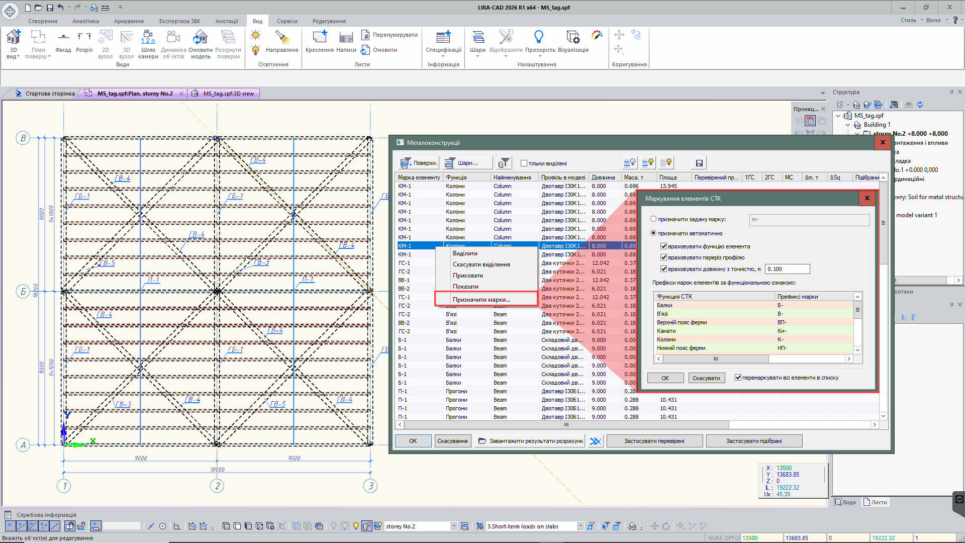
Implemented the Labeling of steel structure elements tool. Labeling can be performed manually (by assigning a specific label) or automatically (with automated label generation).
For automatic labeling, label prefixes must be set according to functional characteristics. Automatic labeling considers the function of the steel element, its cross-section, and the element length with the specified accuracy.
- Added layer search in the “Modeling layers” dialog. Two modes are available: partial and full match. In full match mode, the program also considers uppercase letters. By default, partial match mode is enabled.
- Added multiple selection of sections in the Section parameters dialog using Shift and Ctrl keys. This allows faster creation of section sets, transferring them from the project library to the general LIRA-CAD library, as well as copying and deleting groups of selected items at once.
- In the Default element parameters section of the Program settings dialog, the ability to expand the set of default properties for main objects has been added. Users can preconfigure frequently used and rarely changed parameters, which will be automatically applied when creating new model elements.
- For the function of displaying objects by properties and display modes, the set of visualization options has been expanded. New modes have been added: building layer color, column color by reinforcement type, colors of assembly stages, effective lengths, mass groups, loads, subtask sets, as well as load intensity visualization.
For clearer work in specialized modes, a graphical accent has been added — a frame around the perimeter of the workspace. In Block mode, the frame is displayed in blue, and in Editable analytics mode — in green, allowing the user to quickly identify the current working mode.
Loads
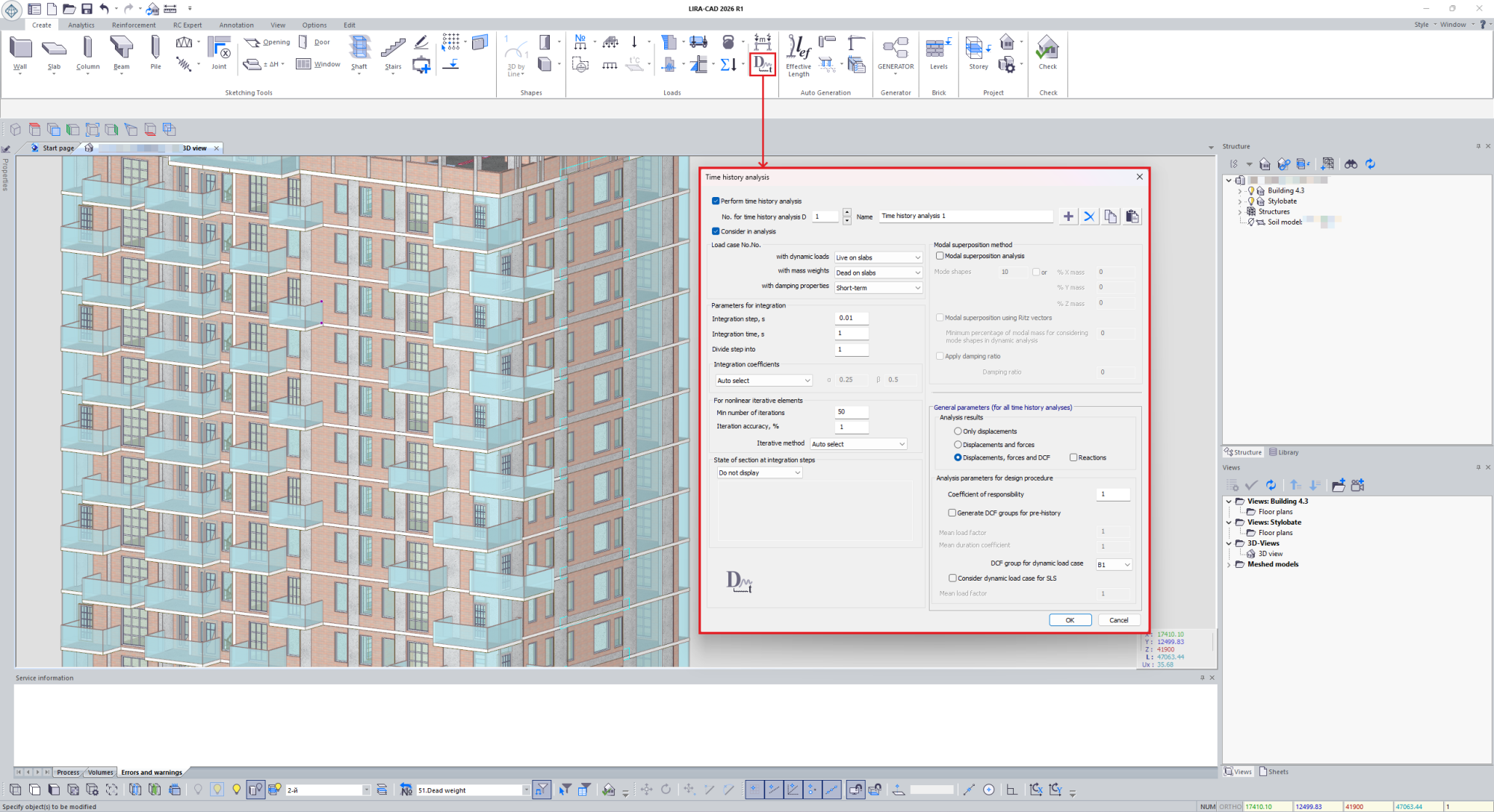
- In LIRA-CAD, parameters have been added for calculating dynamic load using the direct dynamic method with the Time history analysis system.
- Implemented an algorithm for preparing input data for the Mass redistribution groups tool, simplifying model preparation for calculations with mass redistribution.
- Added automatic collection of snow loads on slabs, inclined slabs, variable-thickness slabs, and roof types: single-pitch, double-pitch, and vaulted.
Snow load is collected considering load cases according to standards: DBN V.1.2-2:2006, DSTU-N B EN 1991-1-3:2010, NP to SP RK EN 1991-1-3:2003/2017, and SNIP 2.01.07-85.
- Added the ability to define a snow mound on inclined surfaces.
-
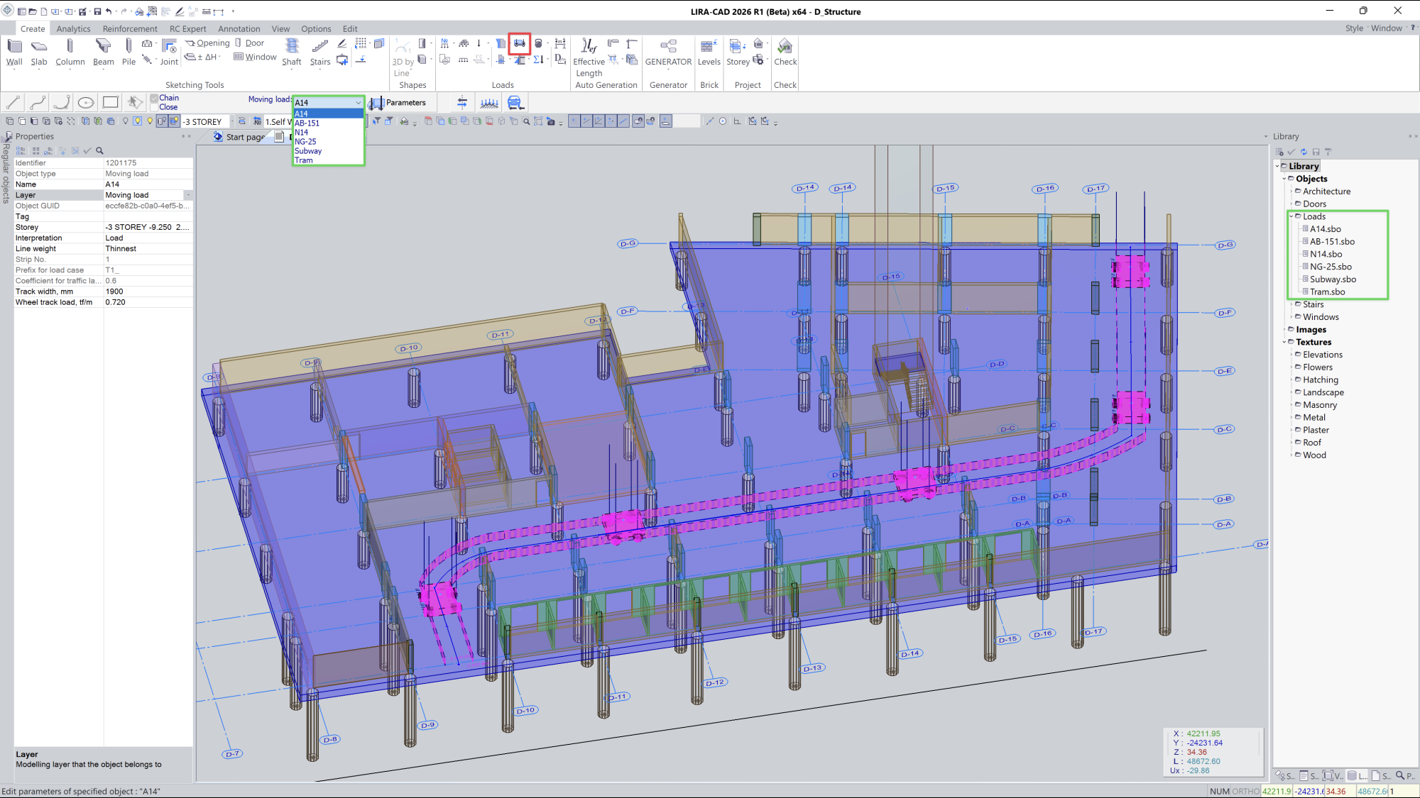
An alternative method of defining moving loads has been implemented, adapted to the standard logic of LIRA-CAD tools.
All moving loads from the library are now available directly in the Moving load command properties panel. The user selects the command, defines the trajectory line, chooses the required load from the list, and creates its path in the model.
Custom moving loads can also be created and saved to the library — after that, they automatically become available in the command properties panel.
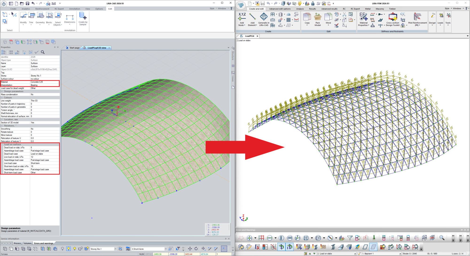
- Added the ability to apply uniformly distributed loads on curved surfaces. Application is performed through object properties.
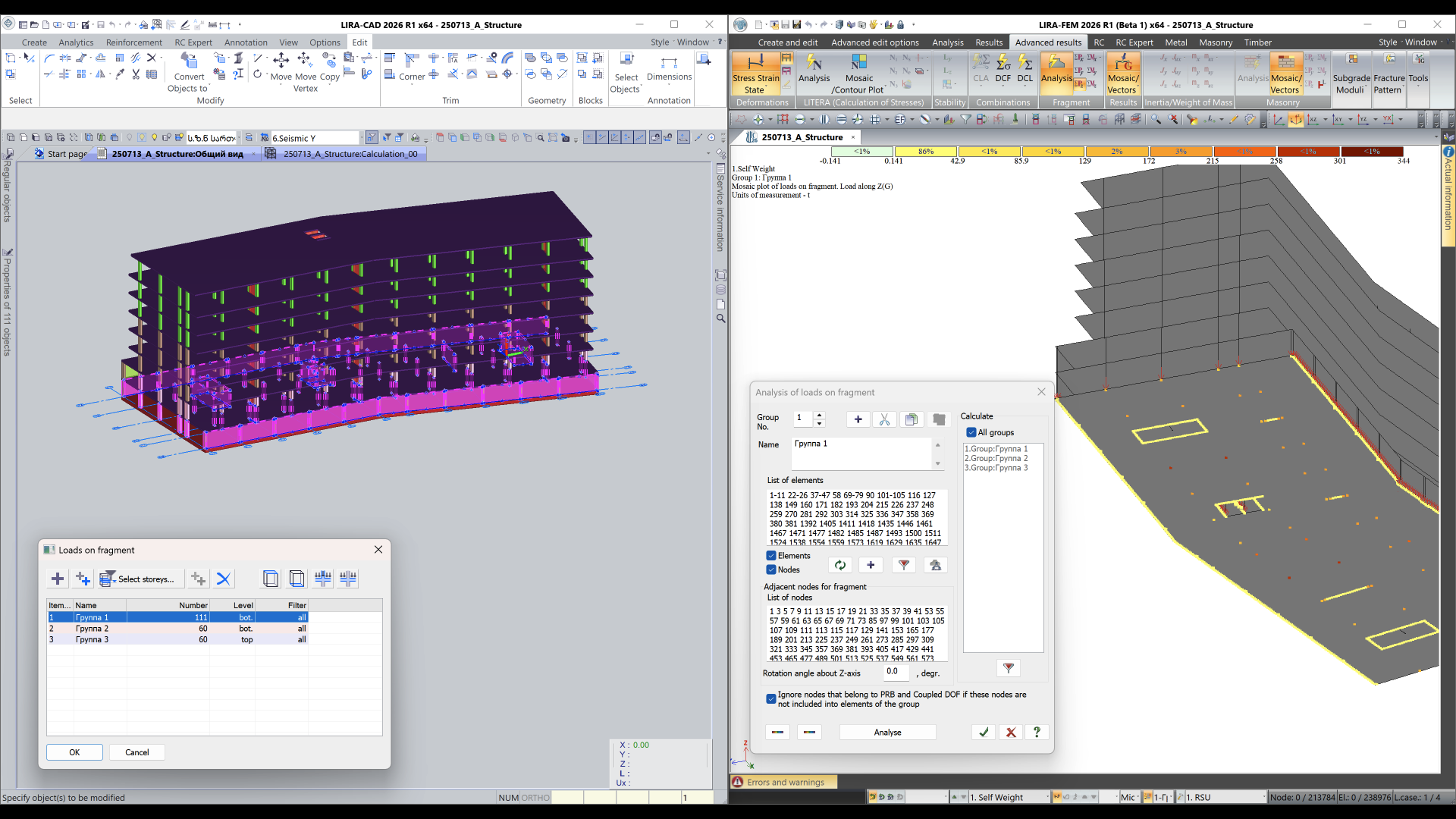
- An algorithm has been implemented in LIRA-CAD for preparing input data for Fragment load calculation. This allows automatic creation of data for collecting loads on walls and columns without additional refinement of the design model in LIRA-FEM.
- Improved logic for determining loads during formation of additional assembly and post-stage loads. An Assembly load parameter has been added to all loads and load-generating objects.
- In the Object visibility filter dialog, load display management has been expanded: separate visualization and hiding parameters have been added for concentrated loads, linear loads, and surface loads.
- Load commands on the ribbon have been reorganized. The load panel is now structured by load content rather than by construction method, as before.
Analytical model
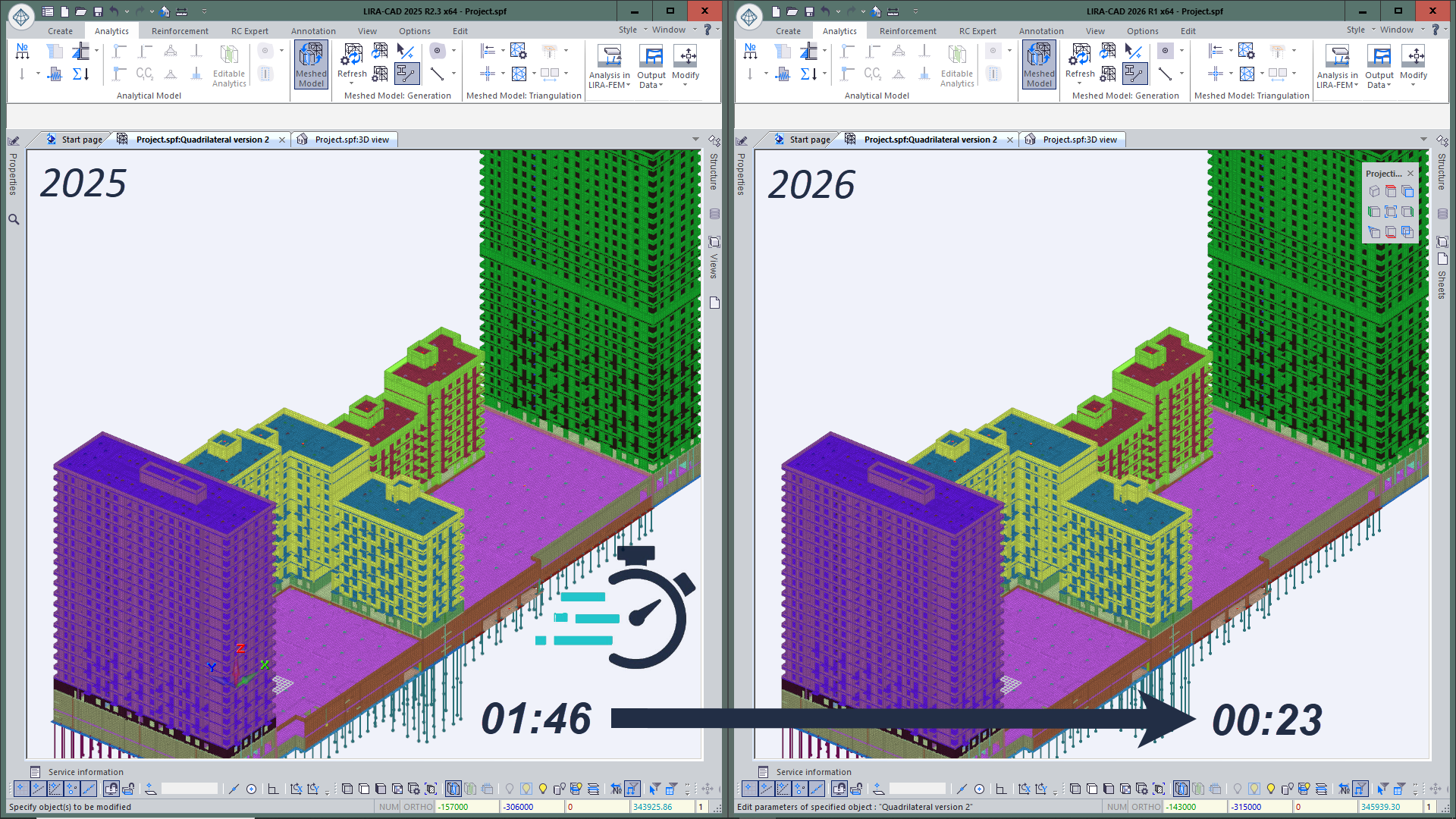
- Accelerated the triangulation process by 2–4 times (compared to previous versions of the program), allowing faster preparation of the model for analysis even when working with complex geometry and large design models.
-
Implemented the Analytical plane tool, designed for aligning and binding model objects relative to a specified plane.
The plane can have vertical, horizontal, or arbitrary orientation and can be used as a base reference element alongside axes and storeys. Objects aligned to the analytical plane maintain associative dependency: when the plane position changes, they are automatically rebuilt.
Two interaction options are possible:
- full binding of the object to the plane;
- snapping/trimming the element to the plane at its start or end (e.g., for walls and beams).
This tool simplifies parameterization and alignment of the BIM model, enabling geometry control without manual adjustments.
-
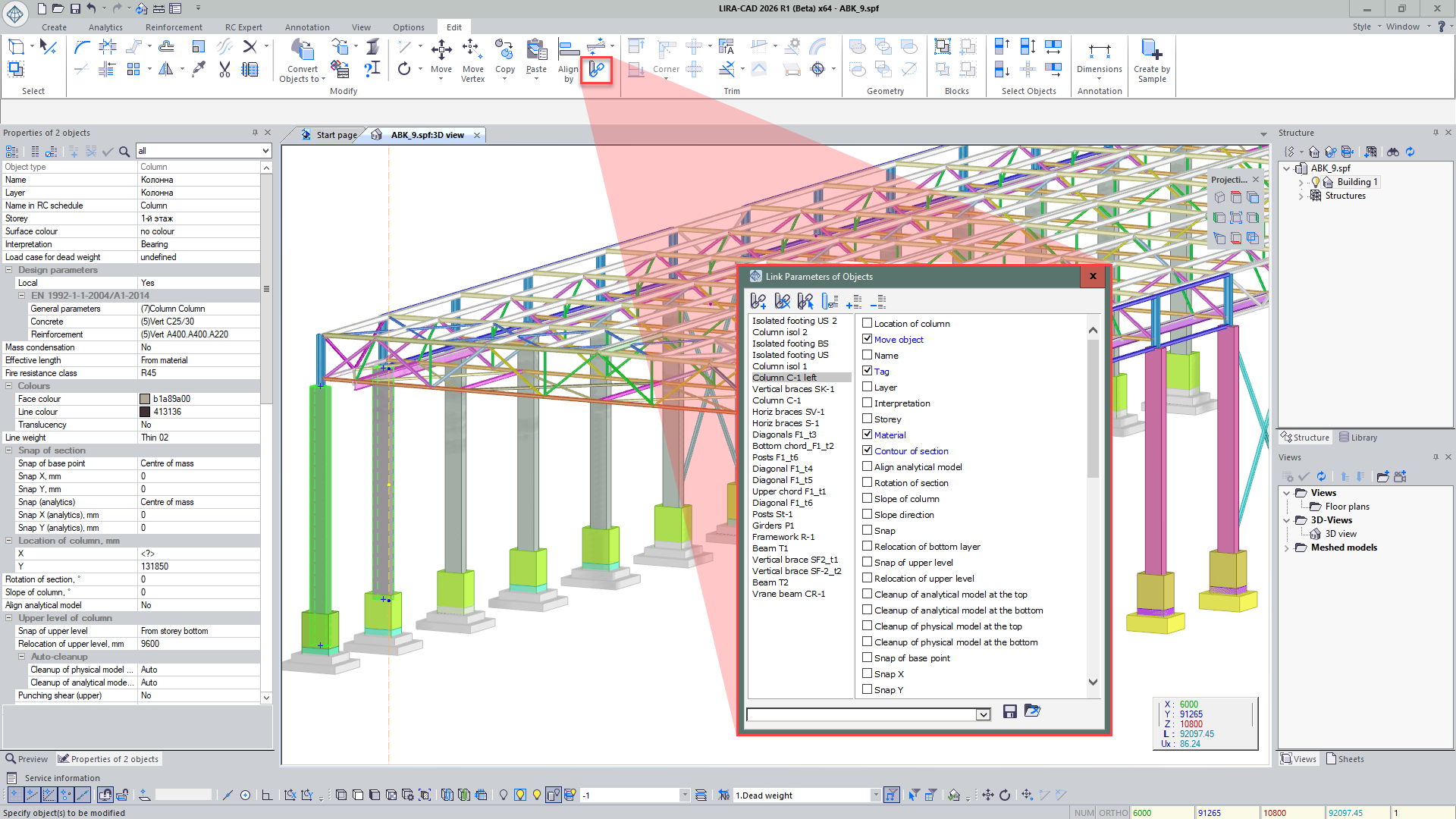
Added new functionality to the “Link object parameters” dialog:
- A list of linked object groups is now displayed — with the ability to select them on the model and identify the sample object;
- When selecting an object on the model, it is now easy to see in the dialog which group it belongs to and by which parameters it is linked;
- For each object, an “Object transfer” parameter has been added, allowing automatic movement of linked objects following the sample — even if they are located on different storeys.
-
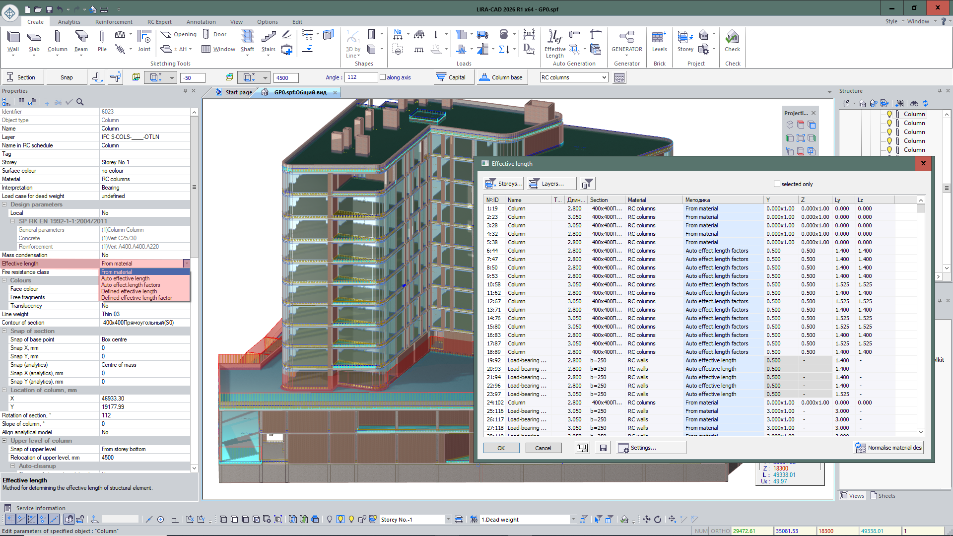
Implemented assignment of effective lengths for reinforced concrete elements. Previously, effective lengths were determined based on material properties. In the current version, additional methods have been added: manual input, as well as automatic determination of length or effective length factor.
For convenience, summary table of effective lengths has been implemented. It allows centralized viewing, control, and editing of parameters for all model elements.
- For the Editable analytics mode, tools have been added to adjust the analytical representation of the model without changing the physical geometry. Implemented trimming of analytical wall plates and analytical beam bars, simplifying preparation of the design model, improving accuracy of the analytical model, and speeding up its editing.
- Expanded checks of input data correctness when creating the design model. Added verification of the presence of a linked soil model: if the task specifies linking a soil model to the building but the model is not found, the program warns the user.
- When generating a design model only for selected objects, error checking is performed exclusively for those elements. The display of data in the Project service information dialog has also been updated: errors and warnings are shown for the active project.
- Automatic organization of wall-column interaction is implemented both when trimming the wall edge by the column body and when splitting the wall into parts by a column located inside it. The analytical wall plate is trimmed by the physical dimensions of the column, and joint action of elements is established through PRB (perfectly rigid body).
- For controlling such connections, the Object connection management tool has been added, allowing viewing of linked elements, selecting them on the model, and removing them from the connection if necessary.
- Improved formation of models created by the Hyperbolic paraboloid tool. For flat variants of such objects, redundant triangulation lines (needed only for non-flat surfaces) are no longer created.
- The Triangulation splitting parameter allows flexible control of triangulation and formation of a higher-quality finite element mesh for this type of object.
- For walls forming a Bar analogue object, a set of improvements has been implemented for better preparation of analytical and design models. New settings have been added to BA parameters: Labeling, Extreme node search zone, and Intersect.
-
If another wall adjoins a partition with a bar analogue and the BA line is close to the line of wall interaction, the program can shift the BA to the junction line considering the Match accuracy parameter.
This allows forming a more correct finite element mesh without elongated elements of incorrect shape.
- New parameters provide flexible control of BA and FE mesh formation in the wall junction zone. With Intersect = No, the bar analogue is formed without shifting, while maintaining correct finite element shapes.
- When transferring BA to LIRA-FEM, data is displayed in the Structural blocks dialog: the label of the main element, BA label, comment with the name of the source element and the prefix Bar analogue, as well as the storey location of the element.
- Added support for transferring non-standard sections from LIRA-CAD to LIRA-FEM with interpretation as equivalent cross-sections, allowing more accurate consideration of specific frame element sections in calculation.
Beam / Cable
- In the Locate section dialog, the ability to adjust the position of the analytical bar for a group of selected beams has been implemented. This allows setting the correct placement of analytical bars for the entire group of elements in a single operation without editing each one individually.
- For more convenient work and clearer evaluation of analytical bar snap parameters, the corresponding properties have been moved to the object parameters. Now the user can directly view and edit the selected snap option: At the center of the bounding box, At the center of section mass, at the corners and sides of the section, as well as the snap values of the binding point along X and Y axes. This simplifies control of assigned parameters and speeds up adjustment of the analytical bar position.
- For more precise control of beam placement in the model, separate snaps have been added at the start and end of the bar. For each beam point, the standard set of snaps can be used: Free snap, From floor top, From floor bottom, and Specified level. This simplifies model generation and further editing of beam positions.
- A mechanism for explicitly defining relationships between beams has been implemented. Connections are formed based on PRB and displayed in the analytical representation even before the design model is generated, ensuring more accurate control of modeling logic and clear verification of connections between elements.
- For “Cable” objects, a new generation method has been added — “Catenary line”. It simplifies modeling of cable-stayed structures with a specific sagging shape that must be considered in both the physical and design models.
Slab / Stairs
-
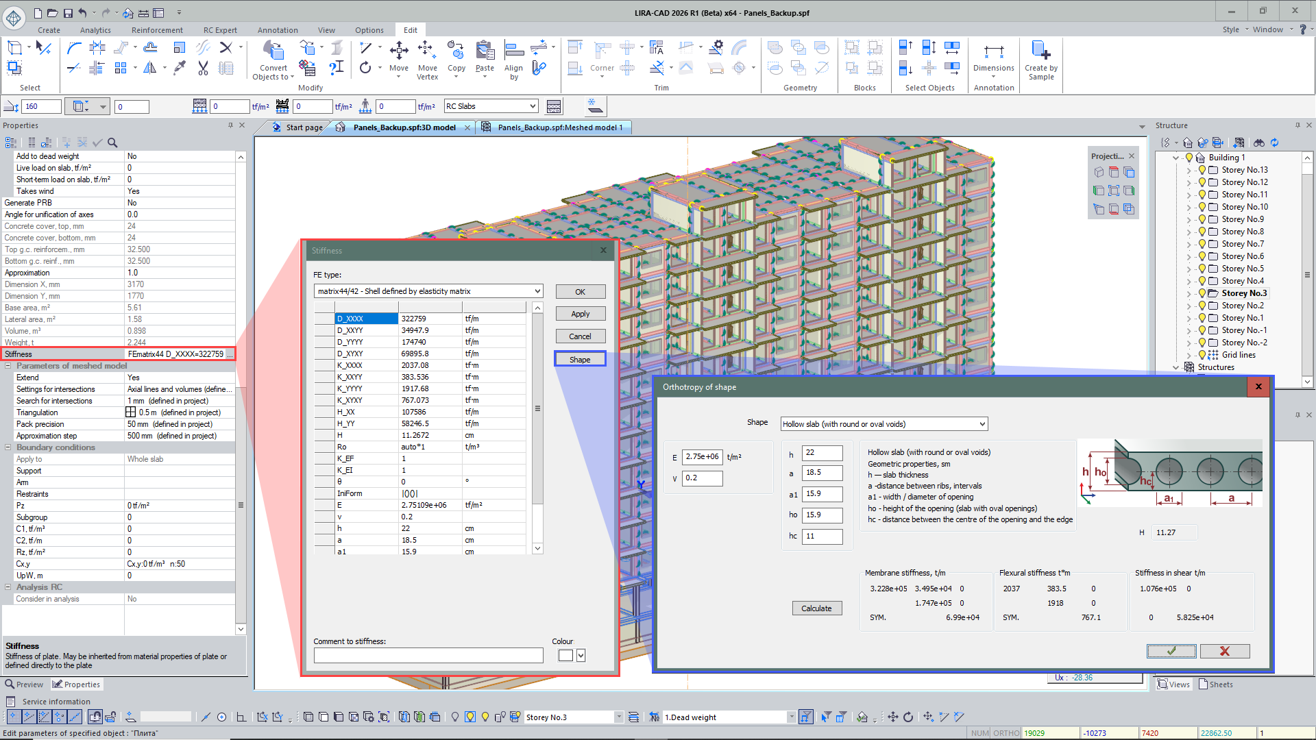
For slabs, an additional function has been developed to account for shape orthotropy.
In the dialog box, the user can select the type of structural slab form and specify the necessary geometric parameters to determine its reduced stiffness and calculation behavior.
The following options are supported:
- one-way ribs in one direction;
- two-way ribs in one direction;
- one-way ribs in two directions;
- one-way box slab;
- two-way box slab;
- beam grillage;
- corrugated decking;
- wavy corrugated decking;
- slab on corrugated decking;
- hollow-core slab with circular or oval voids;
- solid slab.
- Added the option to select self-weight loading for inclined slabs and stairs.
- Added an alternative method for editing an inclined slab with free top and bottom binding.
- Improved load generation from spaces for inclined slabs.
Storey
-
New functionality has been added to the Storeys dialog:
- creation and deletion of storeys;
- editing the height and marks of storeys, including for groups of storeys;
- assigning names to levels and storeys;
- assigning a level by mark.
- Commands Enable transparency and Disable transparency have been added to the project tree context menu. The degree of transparency is set in the Visualization settings dialog using the Element transparency parameter.
- In the new version, the individual position of the local coordinate system defined by the user is preserved. When switching between storeys, its orientation does not return to the initial state but remains in the previously configured position — at the required angle or with the necessary alignment to the object.
Shaft
- For shafts, a Display on all floors parameter has been added, allowing their visibility to be maintained regardless of the current model level. This simplifies control of shaft placement in a multi-story structure, especially when working in Show active floor mode. The function is equally supported in both the physical and analytical representations of the model.
- The trimming mechanism for shafts has been expanded: openings are now generated not only in slabs but also in loads intersected by the shaft contour.
- An option has been added for conditional marking of shafts with fill, improving the clarity of their placement in the model and simplifying object selection during editing.
- For spaces, the handling of shafts and openings has been refined: if a shaft passes through a space or an opening is located within it, the corresponding volume is excluded from the space, and loads in these zones are not generated.
Openings / Door and Window opening
- Added an option for conditional marking of openings with fill, which simplifies visual analysis of their placement in the model and makes object selection more intuitive.
- Door and window openings modeled as loads from panels can now participate in staged construction modeling of the building and be used in the Assemblage tool.
- Improved display of overall dimensions for openings and voids. When objects are selected, their dimensions are dynamically displayed, allowing more precise control of opening sizes in model elements. In the new version, permanent display of the linear dimension along the length of the opening has also been implemented. The dimension line clearly shows the object’s size and can be used for selection, which is especially convenient when working in top view, where the opening is physically hidden inside the wall or partition.
Axes
- New types of axes have been developed in the program, with the ability to generate along an arc, circle, spline, and Bézier curve.
- Added transformation of a 2D grid of coordination axes into a 3D grid for convenient spatial positioning. Optionally, additional floor levels can be displayed.
- Automated assignment of properties for building axes imported from IFC. Previously, such axes could be duplicated and displayed on all floors, complicating work with the model. Now, imported axes automatically follow LIRA-CAD logic, showing axes only on the current floor, while retaining the option to display axes on all floors if needed.
Wall / partition
- Added the ability to create a niche in a wall. The niche is created using the ±ΔH command.
- Added visualization of Face / Back for the wall. When a wall is selected, a local coordinate system is displayed showing the wall’s position.
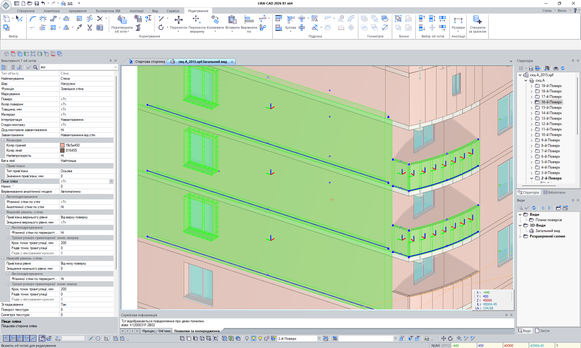
- Implemented correct wall-to-wall trimming for cases where walls are not vertical but angled. In such intersections, both the physical and analytical wall models are formed correctly.
- Implemented wall-to-wall trimming not only for perpendicular and angled intersections but also for cases where elements lie in the same plane. This type of trimming simplifies model construction and speeds up adjustment of imported data when adjacent walls in the same plane partially overlap.
- Improved the trimming mechanism of partitions against load-bearing walls. If a partition is interpreted as a load, the load line now stops correctly at the perimeter of the load-bearing wall instead of entering its volume.
- Changed the mechanism for handling intersections of partitions with load-bearing walls. Previously, elements had equal priority during trimming, which in some cases led to incorrect shortening of the load-bearing wall and distortion of the calculation scheme. Now the load-bearing wall has priority: the partition is always trimmed along the analytical plate of the wall, ensuring more accurate formation of the building’s calculation model.
- Refined the mechanism for forming openings from ventilation ducts in walls: openings are created based on actual intersections with walls regardless of the floor affiliation of elements.
- For partitions interpreted as loads, the mechanism for forming loads when trimming against an inclined plane or slab has been refined. In such cases, the load is determined by the actual trimmed geometry of the partition and is formed not as uniform but as triangular or trapezoidal.
Column
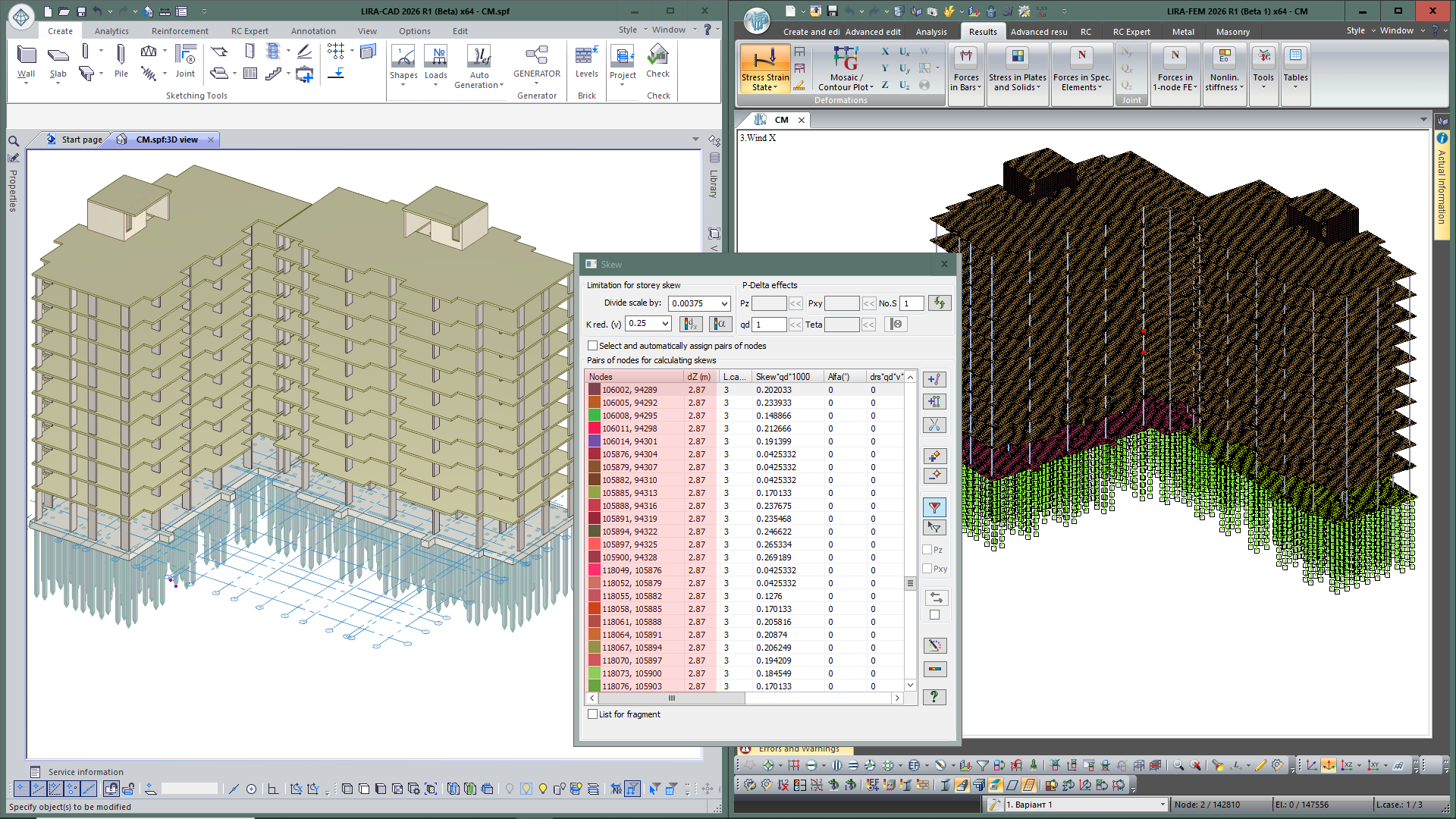
- Added transfer of input data on columns to LIRA-FEM in the form of a pair of nodes for skew calculation.
- Implemented creation of capitals under an inclined slab.
- Implemented multiple selection of capitals and sub-columns with the possibility of further adjustment.
Graphical core
-
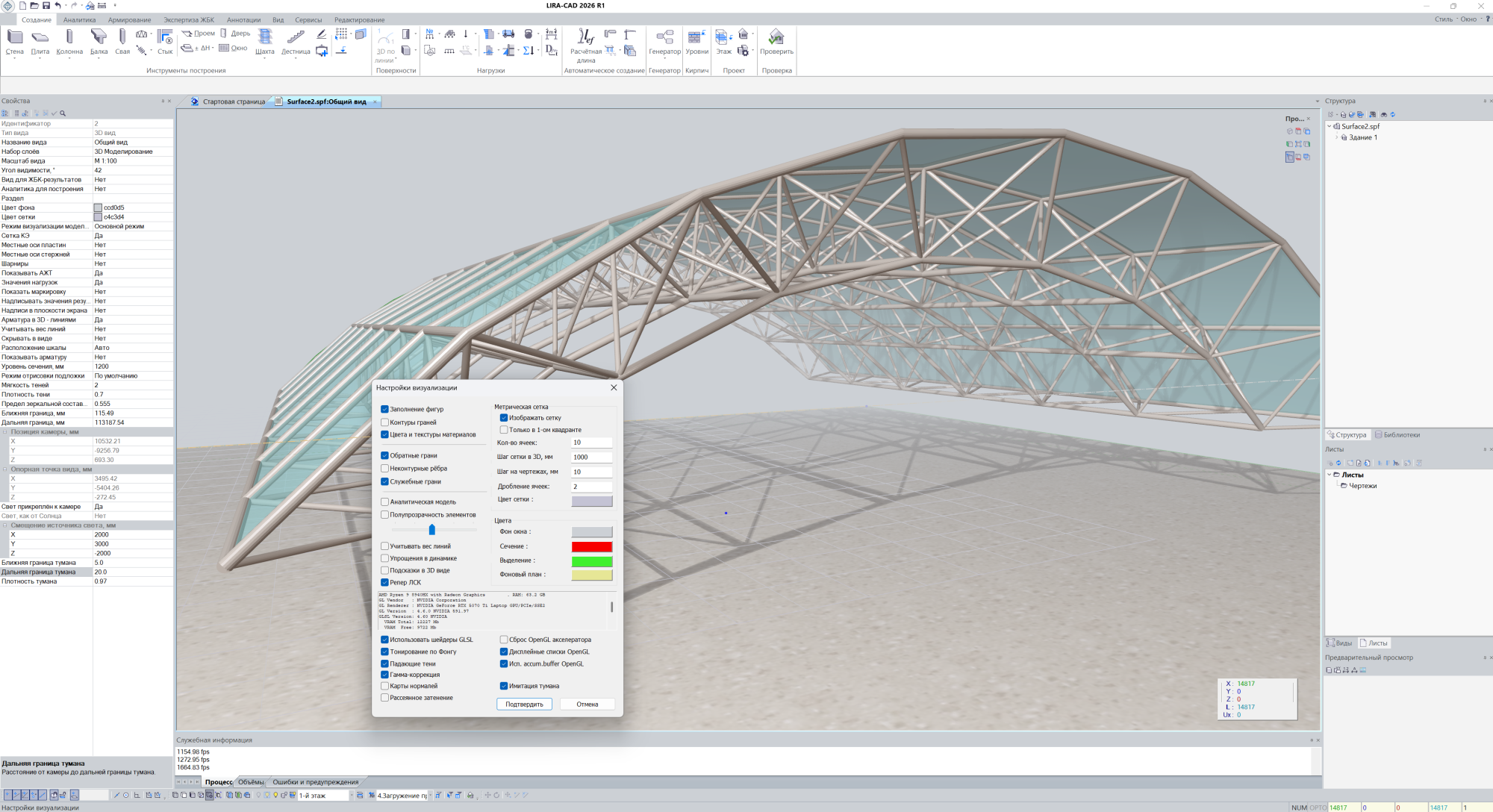
Further development of the LIRA-CAD graphics module based on a programmable rendering pipeline has made our graphics even more expressive and interactive. The speed and quality of visualization have been significantly improved.
Capabilities have been expanded for both the latest hardware and “time-tested” video cards. Alongside existing visual effects such as cast shadows, surface relief, diffuse shading, and others, new features include dynamic “sliding” highlighting of structural elements following the mouse cursor movement, and delayed “lazy” highlighting of structural elements in the area of interest. These reveal hidden geometry and make user interaction with the model more efficient.
Building
-
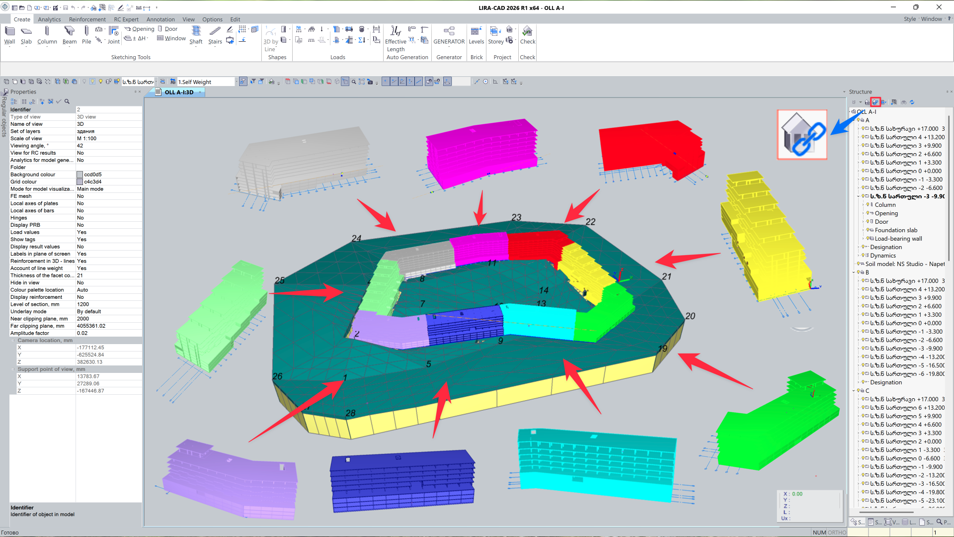
Implemented support for a composite BIM model based on several linked tasks. The “Load building” command allows connecting individual buildings from other projects into the master project not as a copy of geometry, but as dynamically linked objects.
When the source file changes, the connected building can be updated with the “Update building” command without re-import. Along with geometry, materials, loads, assignments, and other configured building parameters are transferred.
Calculation is performed on a single composite model, allowing the object to be considered as a unified spatial system taking into account the mutual influence of all connected parts.
-
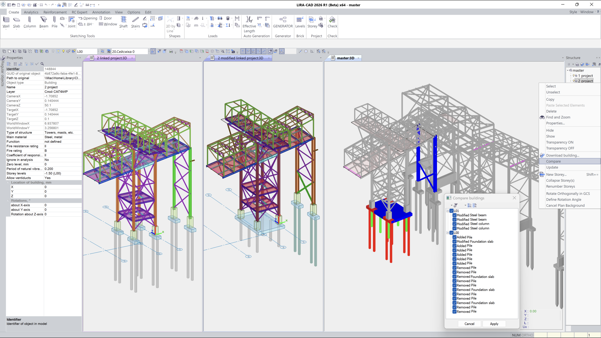
Implemented the “Compare building” function, designed for analyzing model versions and identifying changes between project variants.
The dialog allows displaying:
- added objects — in green;
- deleted — in red;
- modified — in blue.
For convenient work, filtering by structural objects, grouping, and sorting of changes by type, floors, and object types is provided.
- Added a function to create a new building based on selected project objects. The chosen elements are transferred from the current building to the newly created one while preserving the floor structure of the original model.
- Improved project structure handling: in the new version, the user-defined state of the tree expansion is preserved.