Analysis & design of steel structures
In this mode the user could either determine sections of the elements of steel structures, such as trusses, columns and beams, or check specified sections according to building codes.
In the 'Reinforced concrete and steel structures' mode there are options to select and check elements of steel structures and their joints according to ultimate and serviceability limit states.
Selection procedure: for every element of steel structure included into design model the program determines the steel cross-section with min area; the cross-section should take loads defined in design model. To reduce the number of selected cross-sections, elements of design model may be either united into structural elements or unified.
Check procedure: the program makes a check whether steel structures defined in design model will take the specified load.

Analysis of steel structures (metal structures) is carried out according to building codes that contain data about design parameters of steel, dimensions and geometric properties of rolled steel. The user could either add or edit this data in the editable steel tables – SRS module (Steel Rolled Shapes).
Analysis of elements of steel structures
Analysis of elements of steel structures is carried out according to the following building codes:
SNIP II.23-81*;
SP 16.13330.2011;
SNIP 2.01.07-85;
EN 1993-1-1:2005/AC:2009;
DBN V.2.6-198:2014;
SP RК EN 1993-1-2:2005/2011.

Analysis of elements of metal structures is available for the following cross-sections:
- rolled I-sections, welded I-sections, rolled T-sections,
- rolled angle sections, sections from rolled double angles,
- rolled channel sections, welded channel sections,
- C-shaped sections, double channels,
- closed sections,
- laced and battened sections,
- solids and ropes.
For analysis procedure, all elements of steel structures are divided into the following types: columns, beams, trusses and ropes. In analysis of column the program considers axial force, bending moments and shear forces: N, My, Qz, Mz, Qy; in analysis of beam – bending moments and shear forces: My, Qz, Mz, Qy; in analysis of truss – only axial force N; in analysis of ropes – only tensile axial force N+. So, the following analyses may be carries out:
- bearing capacity of beams as flexural elements;
- bearing capacity of beam-column as compressed-flexural and tensioned-flexural elements;
- bearing capacity of columns as eccentrically-compressed and eccentricalle-tensioned elements, as well as axially compressed and axially-tensioned elements;
- bearing capacity of trusses as axially compressed and axially-tensioned elements.
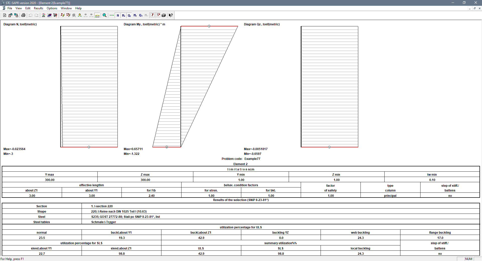
Analysis of bearing capacity of elements of metal structures: output data
Bearing capacity of section according to ultimate limit state:
- strength analysis, including breaking-off, shear, by axial, tangential, reduced (octahedral) stresses
- stability analysis of flexural, axially- and eccentrically-compressed elements, including those where moment is acting in two planes
Bearing capacity of section according to serviceability limit state:
- anaysis of flexural elements for ultimate deflection
- analysis of compressed and tensioned elements for ultimate slenderness ratio
Bearing capacity of section according to local buckling:
- analysis of flanges and webs for local buckling
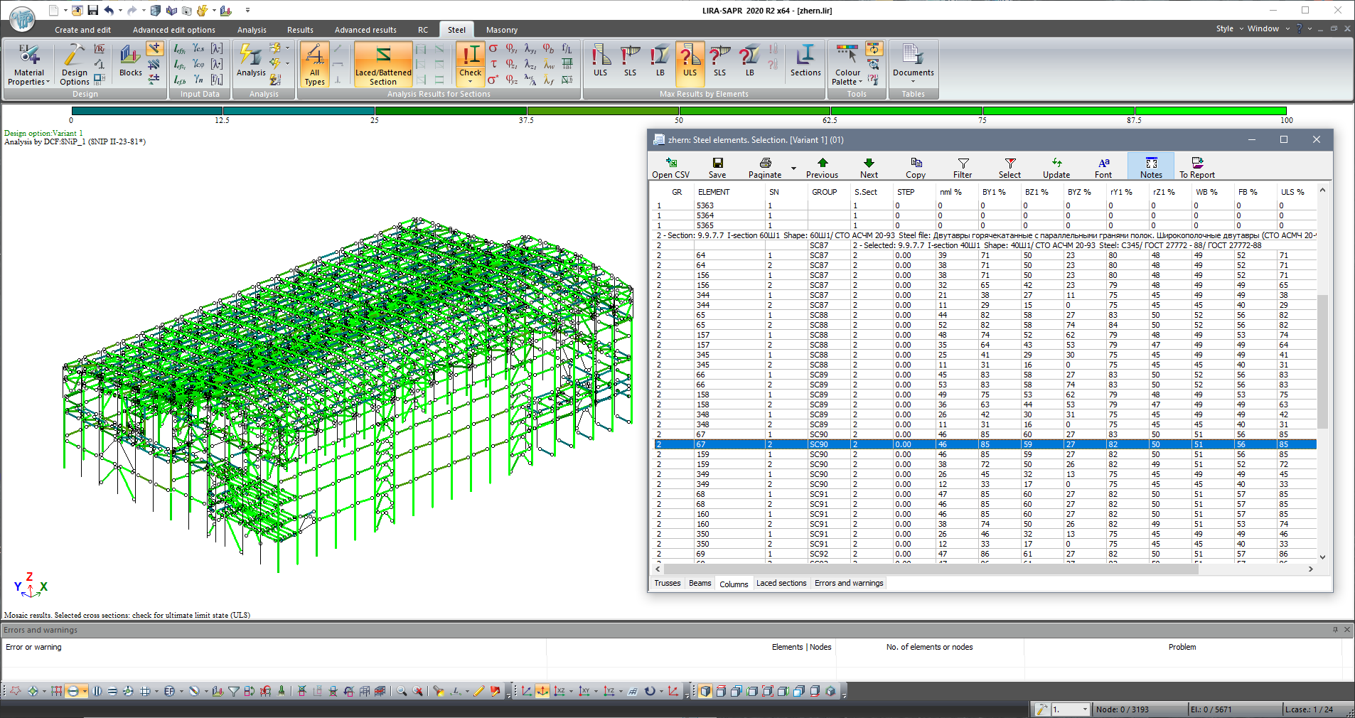
Output data for elements of steel (metal) structures contains mosaic plots and tables with utilization percentage of bearing capacity of elements in specified loads. For further detailed examination, the element of design model may be exported to the STC module.
Joints of steel structures
Analysis of joints is carried out by SNIP II.23-81* and SP 16.13330.2011.

The following joints may be analysed:
- Trusses
- Beam-to-column connection
- Beam-to-beam joint
- Column-to-column joint
- Column bases
- Sway bracings
- Rigid connections
Output data for analysis of steel joints includes dimensions of lacing elements in joint, short report and complete tracing routine for analysis of joint. 3D model as well as drawings of the analysed joint may be automatically generated in KM module.


There is a mode in which the user could generate complex joints from the simple ones. For example, based on simple joints such as beam-to-column joint and brace joint, the user could generate complex joint as three beams and four braces to column. Then it is possible to prepare documentation for such joint in the KM module (the module is intended to obtain (automatically) the complete set of working drawings KM – drawings of steel structures).
While ‘RC and steel structures’ mode in VISOR module provides analysis of steel structures for the whole design model of the building, in the STC module it is possible to analysis and design separate elements and joints of steel structures. Certain element of steel cross-section or certain joint may be transferred from VISOR to STC in order to present the output data in detail.
To search for optimal structural decision, in STC the user could quickly modify cross-section for elements and joints, forces applied to elements, and material properties. The STC module also enables the user to analyse element or joint of steel structures without VISOR tools. In this case, forces, cross-sections and materials for analysis of element or joint should be specified directly in STC module.