

VERSION HISTORY
LIRA-FEM
Analytical model
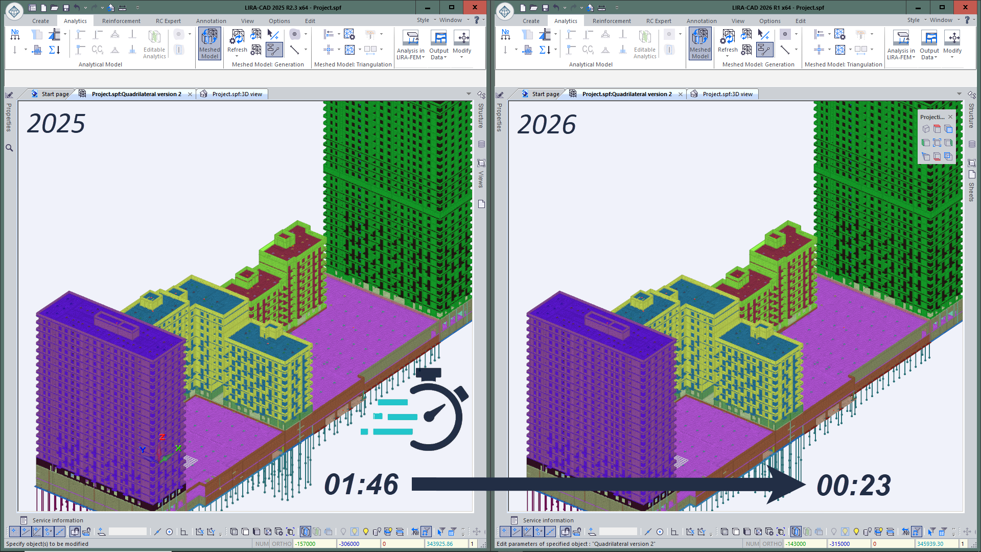
- Accelerated the triangulation process by 2–4 times (compared to previous versions of the program), allowing faster preparation of the model for analysis even when working with complex geometry and large design models.
-
Implemented the Analytical plane tool, designed for aligning and binding model objects relative to a specified plane.
The plane can have vertical, horizontal, or arbitrary orientation and can be used as a base reference element alongside axes and storeys. Objects aligned to the analytical plane maintain associative dependency: when the plane position changes, they are automatically rebuilt.
Two interaction options are possible:
- full binding of the object to the plane;
- snapping/trimming the element to the plane at its start or end (e.g., for walls and beams).
This tool simplifies parameterization and alignment of the BIM model, enabling geometry control without manual adjustments.
-
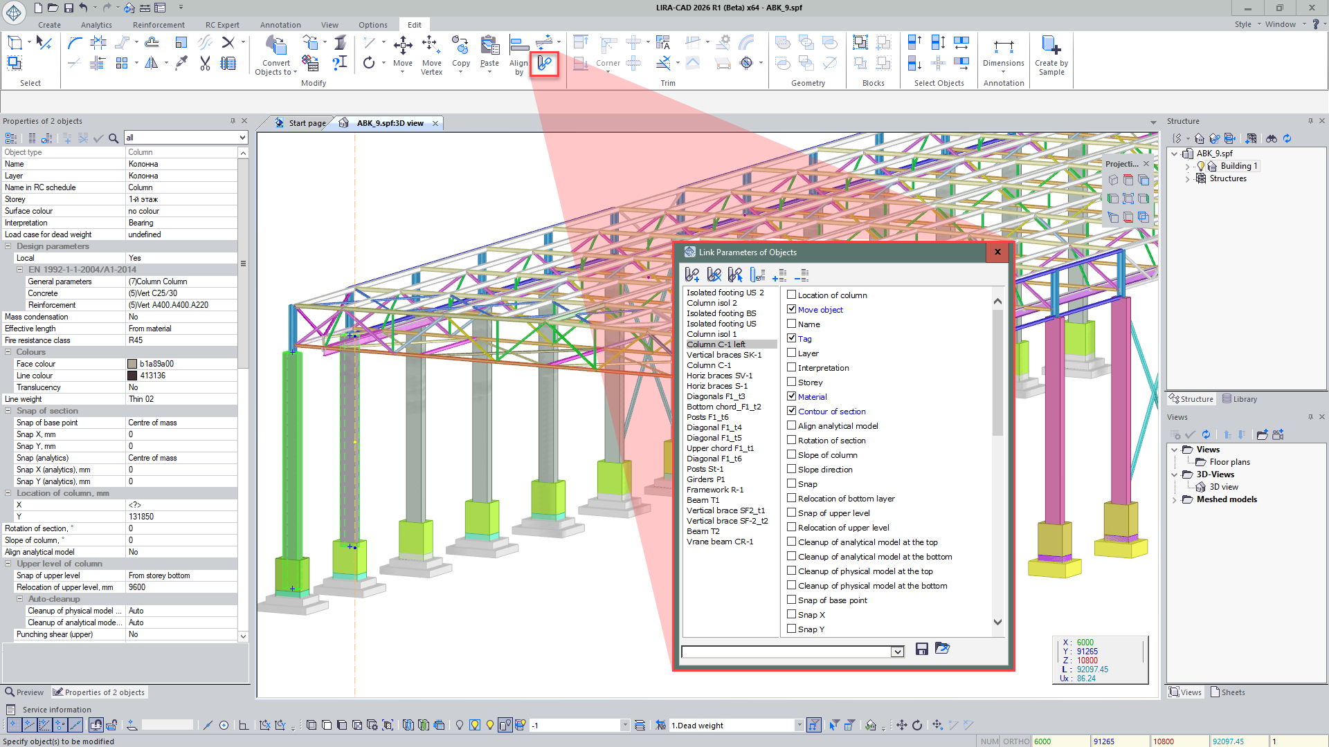
Added new functionality to the “Link object parameters” dialog:
- A list of linked object groups is now displayed — with the ability to select them on the model and identify the sample object;
- When selecting an object on the model, it is now easy to see in the dialog which group it belongs to and by which parameters it is linked;
- For each object, an “Object transfer” parameter has been added, allowing automatic movement of linked objects following the sample — even if they are located on different storeys.
-
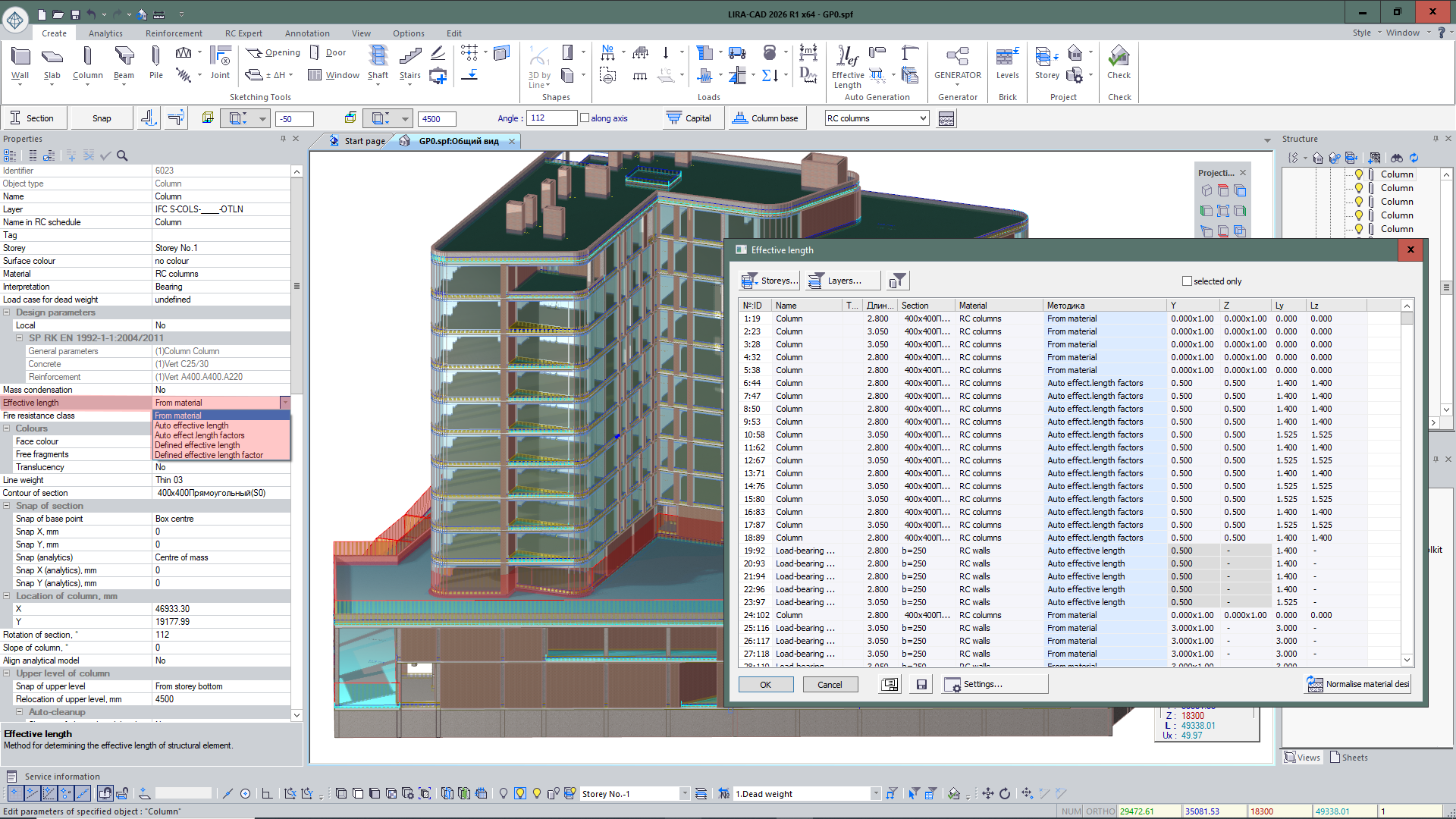
Implemented assignment of effective lengths for reinforced concrete elements. Previously, effective lengths were determined based on material properties. In the current version, additional methods have been added: manual input, as well as automatic determination of length or effective length factor.
For convenience, summary table of effective lengths has been implemented. It allows centralized viewing, control, and editing of parameters for all model elements.
- For the Editable analytics mode, tools have been added to adjust the analytical representation of the model without changing the physical geometry. Implemented trimming of analytical wall plates and analytical beam bars, simplifying preparation of the design model, improving accuracy of the analytical model, and speeding up its editing.
- Expanded checks of input data correctness when creating the design model. Added verification of the presence of a linked soil model: if the task specifies linking a soil model to the building but the model is not found, the program warns the user.
- When generating a design model only for selected objects, error checking is performed exclusively for those elements. The display of data in the Project service information dialog has also been updated: errors and warnings are shown for the active project.
- Automatic organization of wall-column interaction is implemented both when trimming the wall edge by the column body and when splitting the wall into parts by a column located inside it. The analytical wall plate is trimmed by the physical dimensions of the column, and joint action of elements is established through PRB (perfectly rigid body).
- For controlling such connections, the Object connection management tool has been added, allowing viewing of linked elements, selecting them on the model, and removing them from the connection if necessary.
- Improved formation of models created by the Hyperbolic paraboloid tool. For flat variants of such objects, redundant triangulation lines (needed only for non-flat surfaces) are no longer created.
- The Triangulation splitting parameter allows flexible control of triangulation and formation of a higher-quality finite element mesh for this type of object.
- For walls forming a Bar analogue object, a set of improvements has been implemented for better preparation of analytical and design models. New settings have been added to BA parameters: Labeling, Extreme node search zone, and Intersect.
-
If another wall adjoins a partition with a bar analogue and the BA line is close to the line of wall interaction, the program can shift the BA to the junction line considering the Match accuracy parameter.
This allows forming a more correct finite element mesh without elongated elements of incorrect shape.
- New parameters provide flexible control of BA and FE mesh formation in the wall junction zone. With Intersect = No, the bar analogue is formed without shifting, while maintaining correct finite element shapes.
- When transferring BA to LIRA-FEM, data is displayed in the Structural blocks dialog: the label of the main element, BA label, comment with the name of the source element and the prefix Bar analogue, as well as the storey location of the element.
- Added support for transferring non-standard sections from LIRA-CAD to LIRA-FEM with interpretation as equivalent cross-sections, allowing more accurate consideration of specific frame element sections in calculation.