

VERSION HISTORY
LIRA-FEM
Cross section design toolkit
- Added to calculation and output data the following torsional characteristics of the cross-section: sectorial modulus Ww, cm⁴; polar moment of inertia Ip, cm⁴; polar section modulus Wp, cm³; polar radius of gyration Rp, mm.
- Now within section calculation it is possible to use different material stress–strain diagrams depending on the force calculation situation.
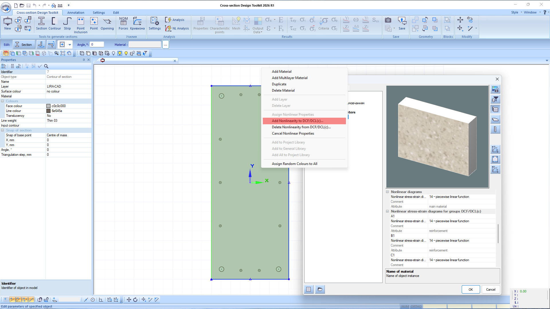
Creation of nonlinear material characteristics for DCF groups
-
Implemented the ability to determine the “moment–curvature” diagram for cross-sections considering material nonlinearity (stress–strain diagrams).
If the obtained dependence corresponds to the requirements of the 34-piecewise linear diagram, the curve can be exported to a *.nll file.
Exported data are used to define the “moment–rotation angle” diagram Mi–φi for one- and two-node finite elements 295 and 296, which model nonlinear hinges.
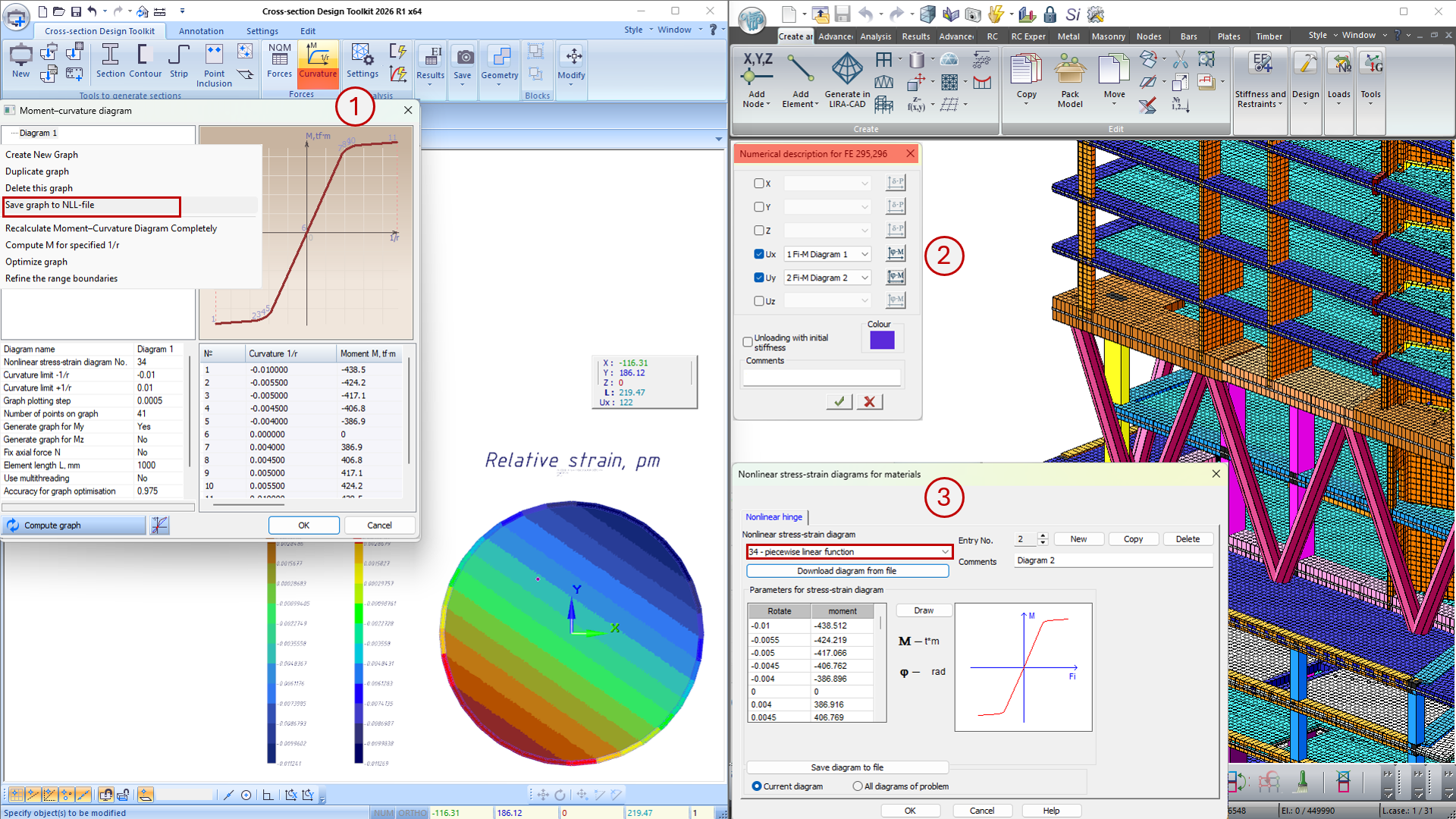
Moment–curvature diagram
- Implemented creation of new sections using the parametric reinforcement type control tool (TA). It is also possible to create sections based on previously formed reinforcement models added to the project.
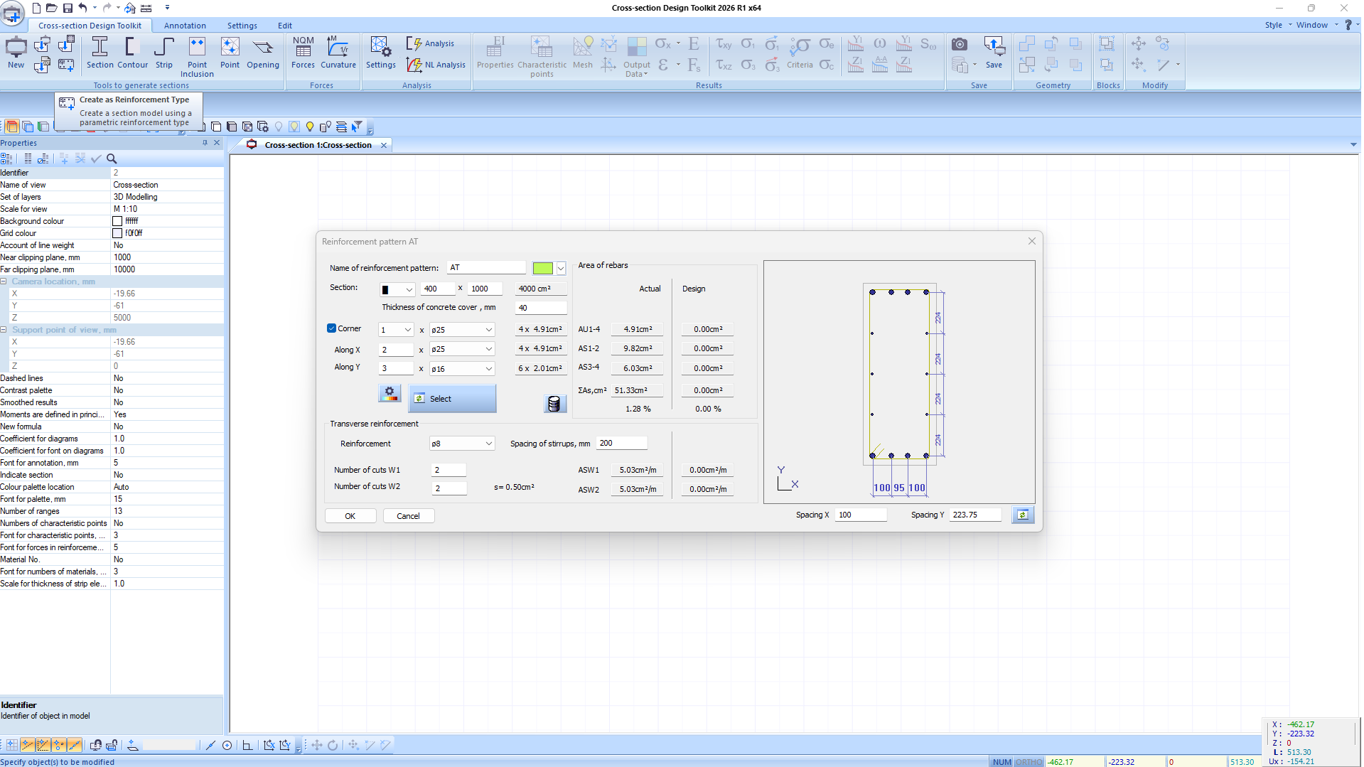
Creation of section using parametric reinforcement type control tool
- The Strip tool, which can be used to model reinforcement elements in the section (profiles, jackets), is now displayed considering the specified thickness.
-
Added new mosaic plots for output data in nonlinear analysis:
- relative strains of bars (point reinforcement inclusions);
- stresses in point reinforcement inclusions.
- Accelerated generation of contour plots for output data and display of triangulation mesh of the cross-section.