

VERSION HISTORY
LIRA-FEM
- Components of BIM technology
- Generating and modifying the model
- Generating and modifying the design model
- Analysis options
- Tools for evaluation of object properties and analysis results
- Analysis & design of reinforced concrete (RC) structures
- RC Expert
- Analysis & design of steel structures
- Soil
- Cross-Section Design Toolkit
- Documentation improvements
Reinforced concrete expertise
RC Expert is a new system in LIRA-FEM program. It is designed to check the reinforced concrete (RC) structures for strength, serviceability and structural requirements. The system offers additional (parallel to the already existing in LIRA-FEM program) technology for analysis of RC structures, focusing on the needs of a wide range of users: designers, experts, researchers.
This system is mentioned to provide a set of checks according to various building codes, where both the analysis algorithms and the input data can be flexibly customized; and more detailed information, including the tracing routines, can be obtained for the certain analysis results. In the first version of the system, structural elements with arbitrary reinforcement pattern and, in the future, with arbitrary cross-sections and/or with strengthening will be analysed. To capture more design situations not covered by the building standards, the analysis algorithms are highly generalised. If generalisation is not possible, the user will receive information on why the modelled structural solution does not fit into the zone of allowed situations according to certain building code.
Arbitrary reinforcement pattern implies that it can be arranged randomly in space, and the user could define various design parameters for individual reinforcement bars or groups of rebars. This will make it possible to analyse the structural elements with defects, corrosion of reinforcement, strengthening during reconstruction, composite reinforcement, etc.
The user could adjust the analysis procedure:
- to select the list and sequence of certain checks, to customize the check procedures, to consider optional items of the building codes;
- to select a list of elements to be checked and a set of valid force combinations for every check;
- to reassign design parameters and coefficients involved in the analysis with user-defined values to control the analysis procedure.
The required transparency of the analysis procedures for the user is ensured by detailed explanations of the methods and assumptions used in the analysis.
The tracing routine is used for a more thorough evaluation of the analysis results in a certain check for a particular combination of loads. By using the tree of intermediate values, the user can follow the steps taken to extract the intermediate values from the input data; the calculation formulas applied in the program code are displayed.

The file is interactive in contemporary browsers; click the line containing a value to reveal the line contents, which include a formula and a list of input values. And so forth, until the user reaches the desired value.
The first release 2025 R1 will implement the strength checks of the bar structural element of rectangular and circular cross-section by the ultimate and serviceability limit states according to DBN B.2.6-98:2009 and EN 1992-1-1:2004/A1:2014, namely:
- check of the normal sections for in axial force and bending moments using a nonlinear deformation model;
- check of crack resistance in normal sections.
Checks for other internal force components, checks using the ultimate force approach, and checks for plane reinforced concrete (RC) elements will be included to this system in subsequent releases.
Localization and regional settings
Start page in the LIRA-CAD module:
- Updated command for project generation: now you can select the required template for a new project.
- Modified command to open the project: it enables you to quickly display and open previously closed projects.
- Enhanced command to import files: now it is possible to specify the type of imported files at once, it speeds up the process. The selected type is temporarily saved for subsequent import operations.
- New commands Case Studies and News are added.
- Enhanced interface for the Start page.
LIRA-CAD Interface:
- All main tools to customize the program options are moved to the Options tab.
- The Shaft and Ventilation duct commands are gathered to one panel.
- New options are added to the Display visualisation command: Tag Colour, Colours for Sets of Subproblem, and Linked by Parameters.
- In the Section parameters dialog box, the list of cross-sections used in the project is now expanded by default.
- Double-click a section to assign it to an element and automatically close the dialog box.
'Materials' dialog box:
- Enhanced functionality of the Materials dialog box: support for SHIFT and CTRL keys, the option to move a group of materials to a general project library, to copy materials and save their GUID.
- When creating custom materials for concrete and reinforcement, you could now specify your own unique name instead of the one suggested in the program.
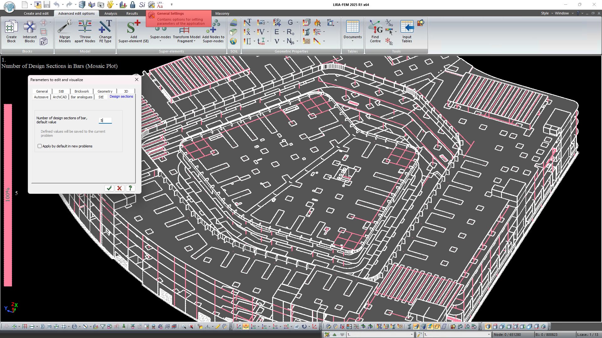
New option to customize the number of design sections of bars that should be added by default for the current and new problems.
Modified output of mixed format for numbers. Now you can define the number of significant digits and the number of significant digits for integer part only.
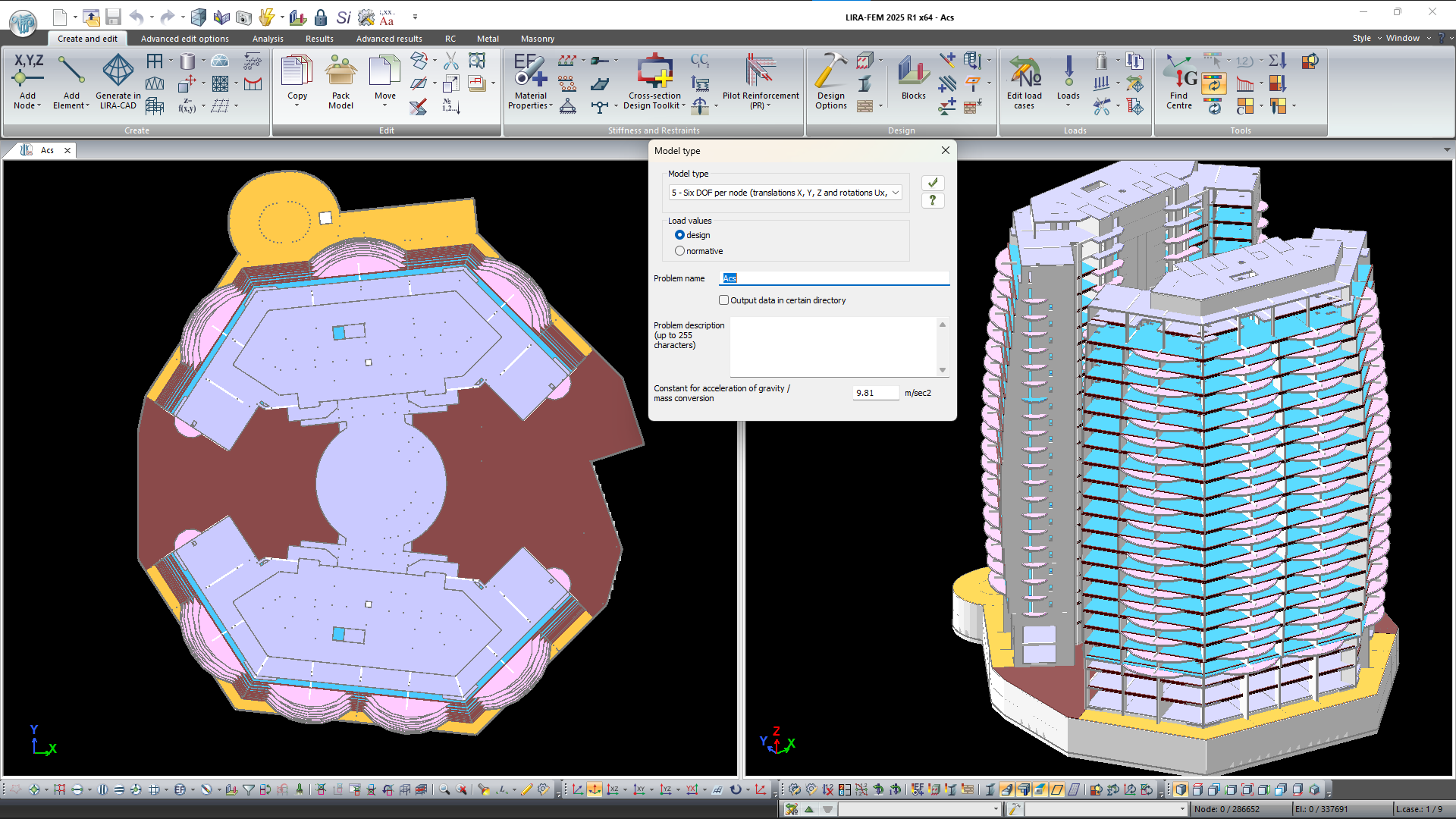
The new option to define the acceleration of gravity is added. So the user could change the default value (g=9.81054 m/s2), when transforming masses for dynamic analyses and when generating the response spectrum for earthquake analyses (SP RK EN 1998-1:2004/2012, NTP RK 08-01.1-2017).
Now it is possible to use shared memory for CPU and GPU. The corresponding option is added to the General program settings. This option will be useful for laptops with integrated video cards.

Improvements to the "Soil" module
Calculation of settlement to check the serviceability and determine the design resistance for foundations according to EN 1997-1:2004. Vertical soil stresses σz at depth z are calculated based on the Boussinesq approach and the superposition principle.

The natural pressure diagram is clarified in the case when the cushion is a load and the cushion is above the relief level.
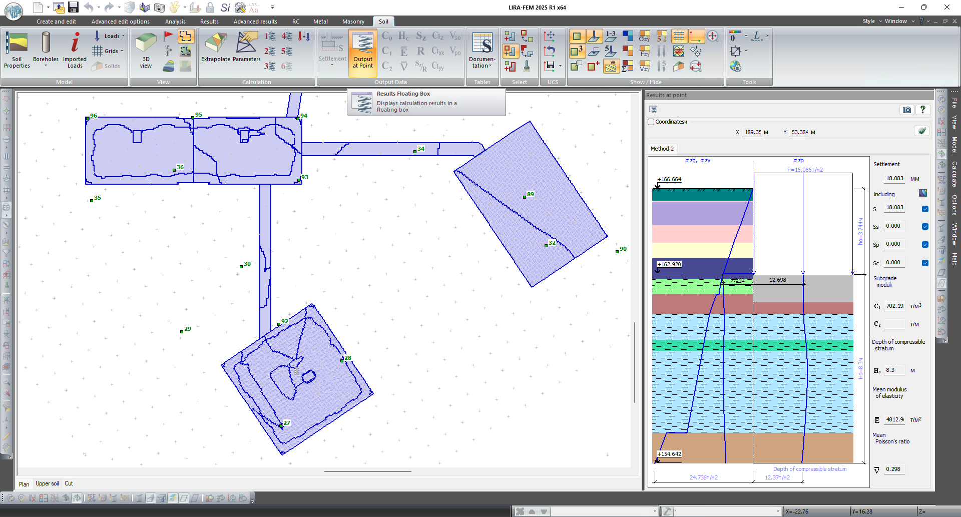
A new algorithm is implemented for calculating settlement and stress values at a specified point of the soil model, without the need to perform a complete analysis.
New option to assign the order of boreholes in the list of boreholes.
For boreholes, it is possible to define a borehole legend (designation).
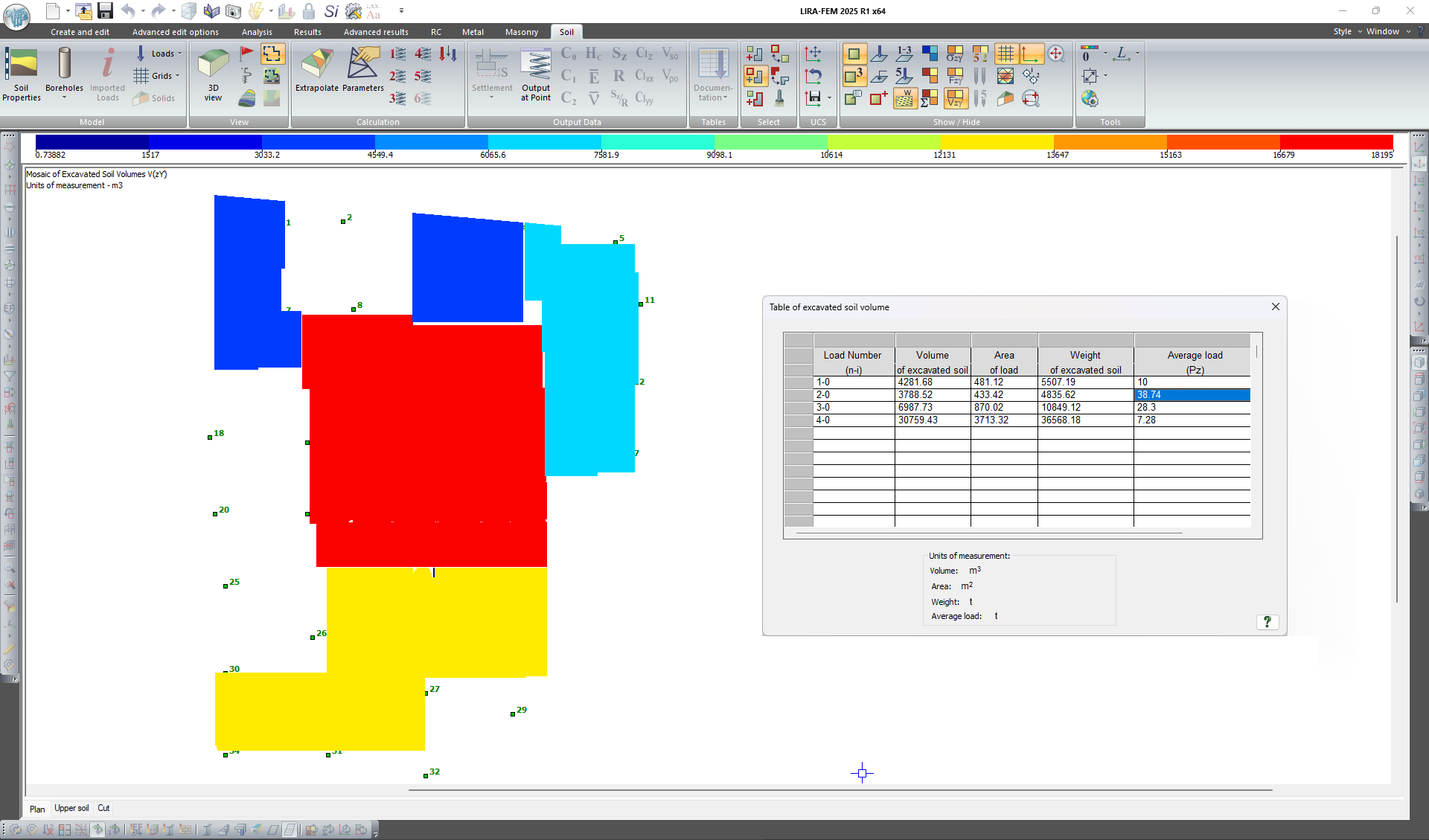
To estimate the initial expenses and volume of excavation operations, new mosaic plots for the weight and volume of excavated soil were created.
New table that displays load parameters (volume, area, weight of excavated soil, and average load value).
New flag of drawing Triangulation mesh for generation of contour plots.
A mosaic plot for groups and subgroups of loads is added to check the input data.
Analysis & design of reinforced concrete (RC) structures
Within the Wall reinforcement type, it is possible to perform analysis of walls and pylons with a detailed arrangement of all rebars and selection of zones of corner reinforcement and reinforcement along edge.

An alternative method is implemented for determining reserve factors for types of pilot reinforcement at a fixed value of axial force.

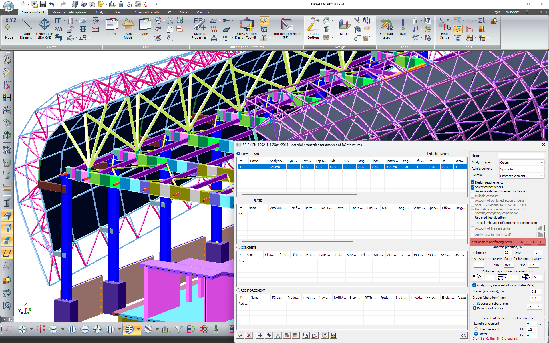
Added option to define additional number of intermediate reinforcing items for increasing reinforcement. This option is available for the following list of element types: bar, column, beam.
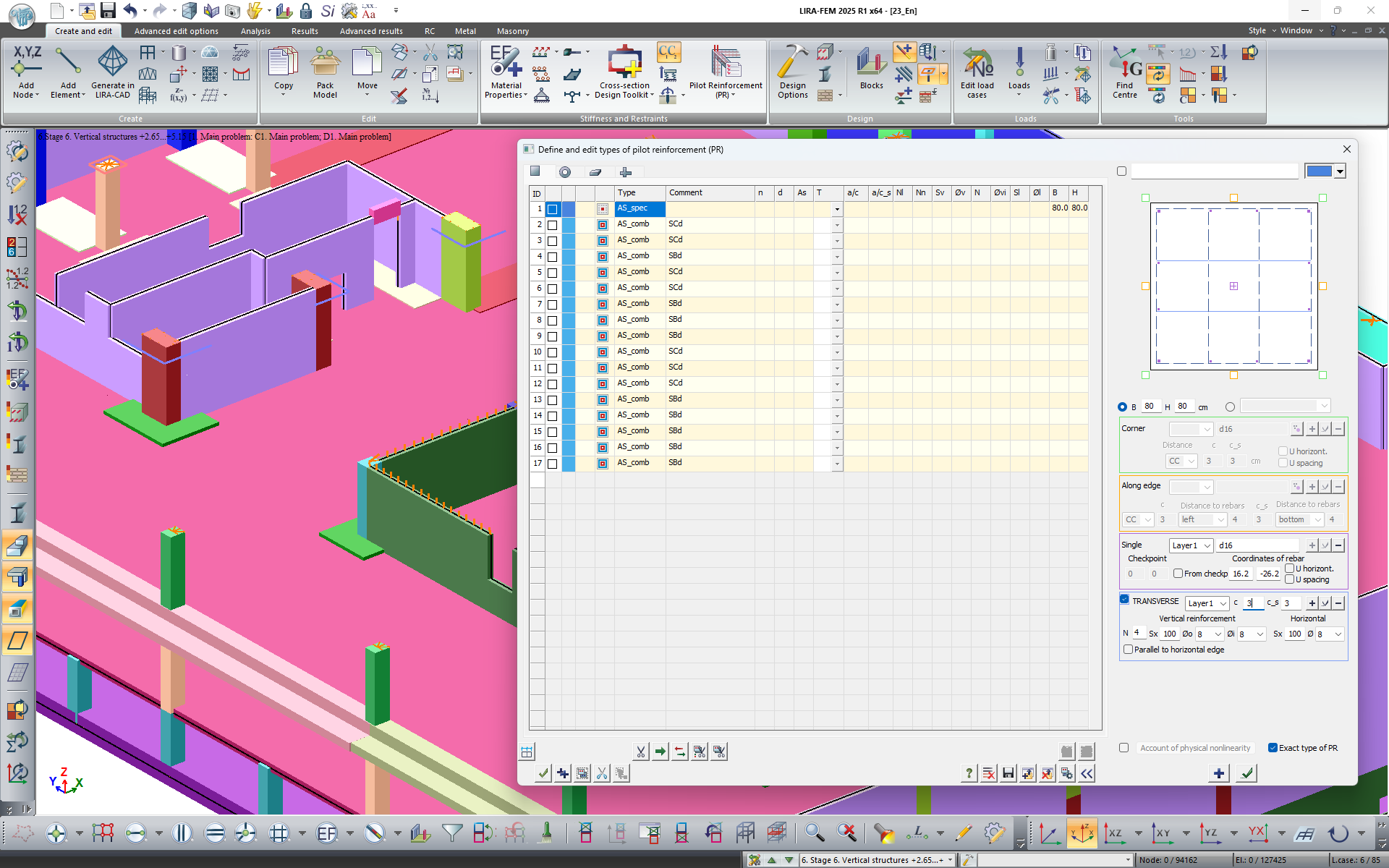
New option to define any number of horizontal cuts of transverse reinforcement to check the types of pilot reinforcement. For the exact type of PR, there is an option to create several layers of transverse reinforcement.
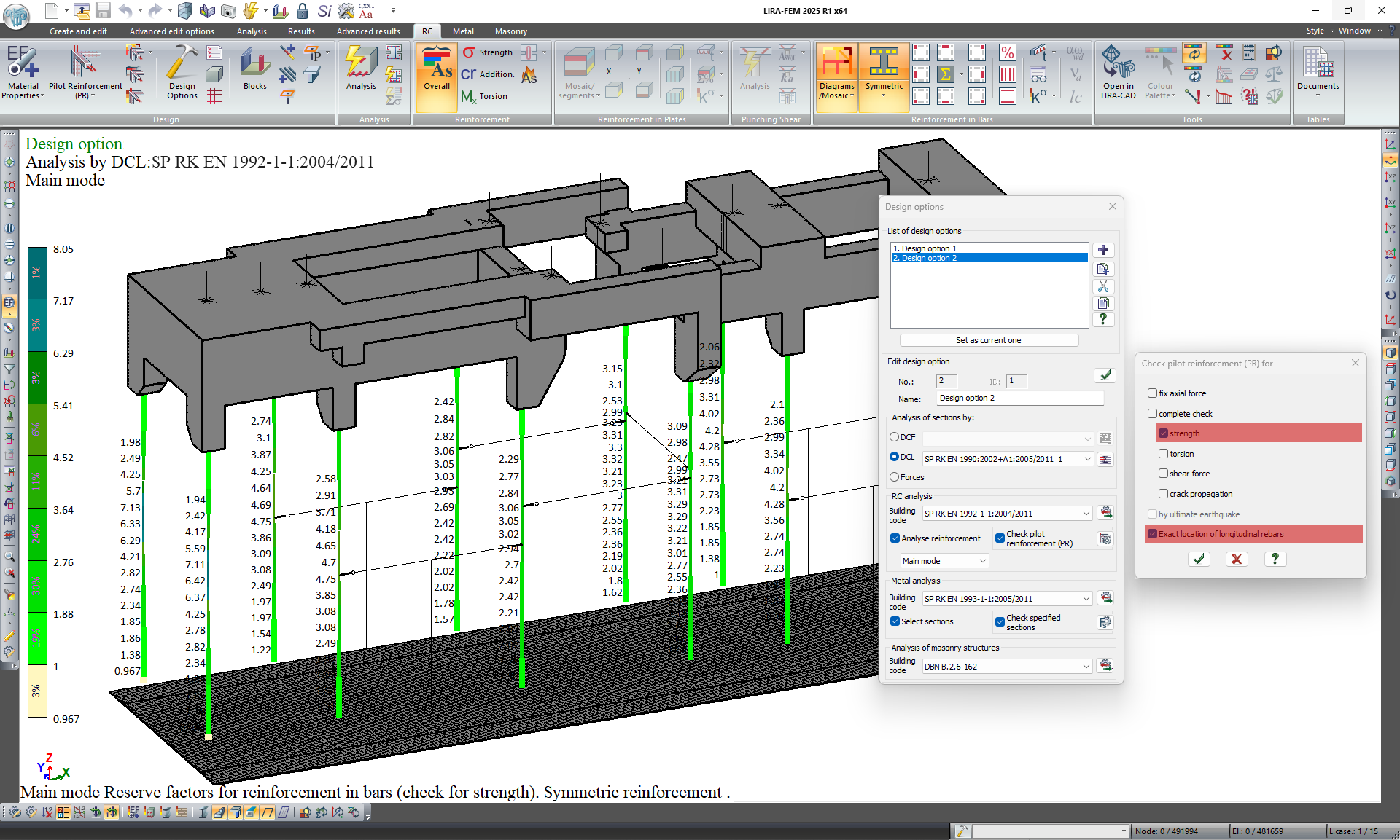
For the check of load-bearing capacity, the user could define an exact location of the reinforcement bars without grouping them into zones as is done for a complete analysis, e.g. with account of torsion.
New option to create and edit names of custom materials: concrete and reinforcement.
Bar and plate analogues
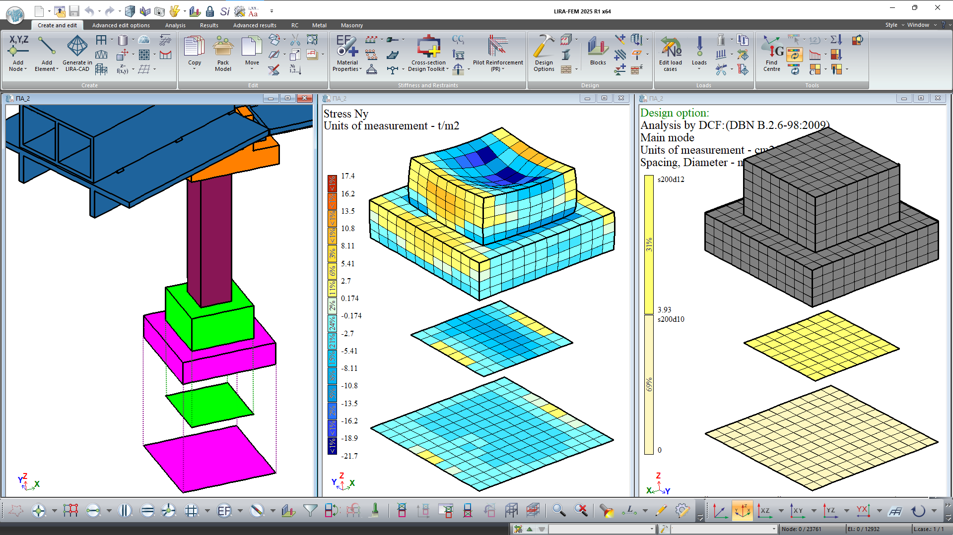
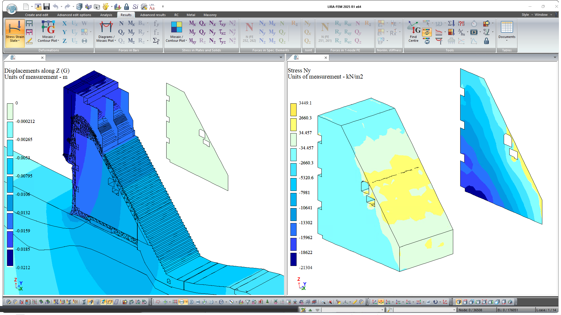
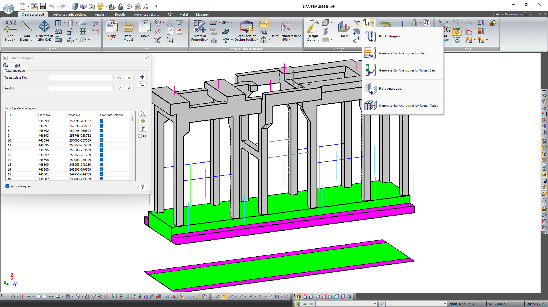
The user can perform analysis of composite structures modelled by a set of 3D elements as plates using the system Plate Analogues.
The concept of plate analogues (PA) is that the resulting forces at the centre of the target plate of a PA are calculated from the stresses in the initial 3D elements. PA membrane forces are obtained by integrating normal and tangential stresses over the thickness of the structure; bending moments are obtained by integrating the product of stresses over the corresponding coordinate over the thickness; and shear forces are obtained by integrating tangential stresses over the thickness.
Modelling of engineering objects, such as large thickness foundation slabs, arch vaults, tunnels, multi-layer structures, retaining structures and hydraulic structures (dams, weirs) is often carried out using 3D finite elements. However, this approach can limit the subsequent design stage of these objects. When the Plate Analogues are used for these structures, it is possible to design plate analogues (select and/or check the specified reinforcement in RC elements, check strength in masonry and masonry reinforcing structures, select meshes and longitudinal reinforcement in walls) based on the obtained internal forces in the target plates (PA).

Improvements to the "Cross-Section Design Toolkit" module
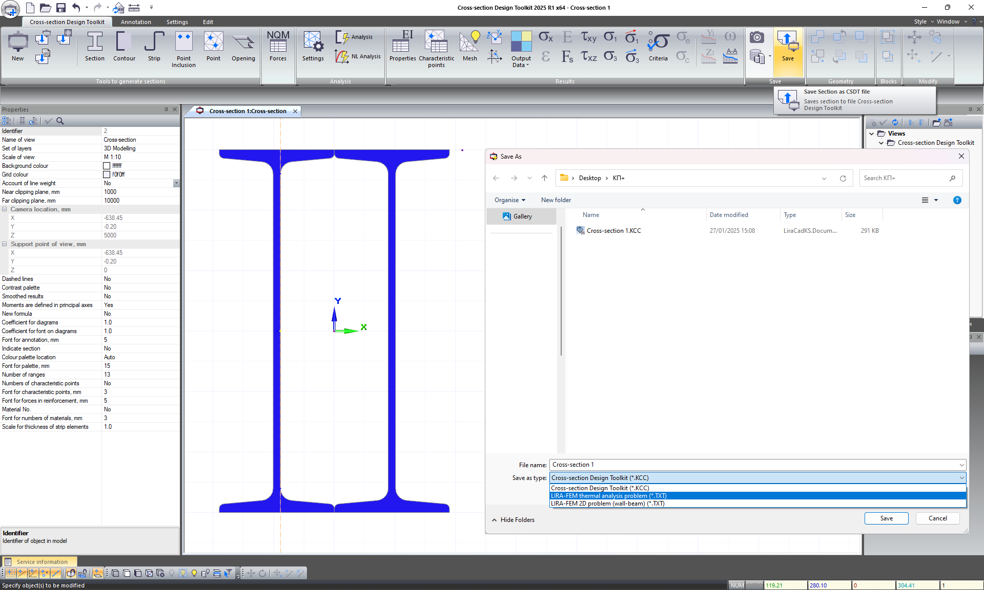
This module now offers the new option to export files to the 15th model type in the LIRA-FEM software. This feature allows the user to quickly generate design models for the problems with heat transfer analysis. During the export procedure, the proper finite element types and stiffnesses are assigned to all elements; convective heat transfer elements are moved along the outer contour of the section to simulate boundary conditions and external loads.
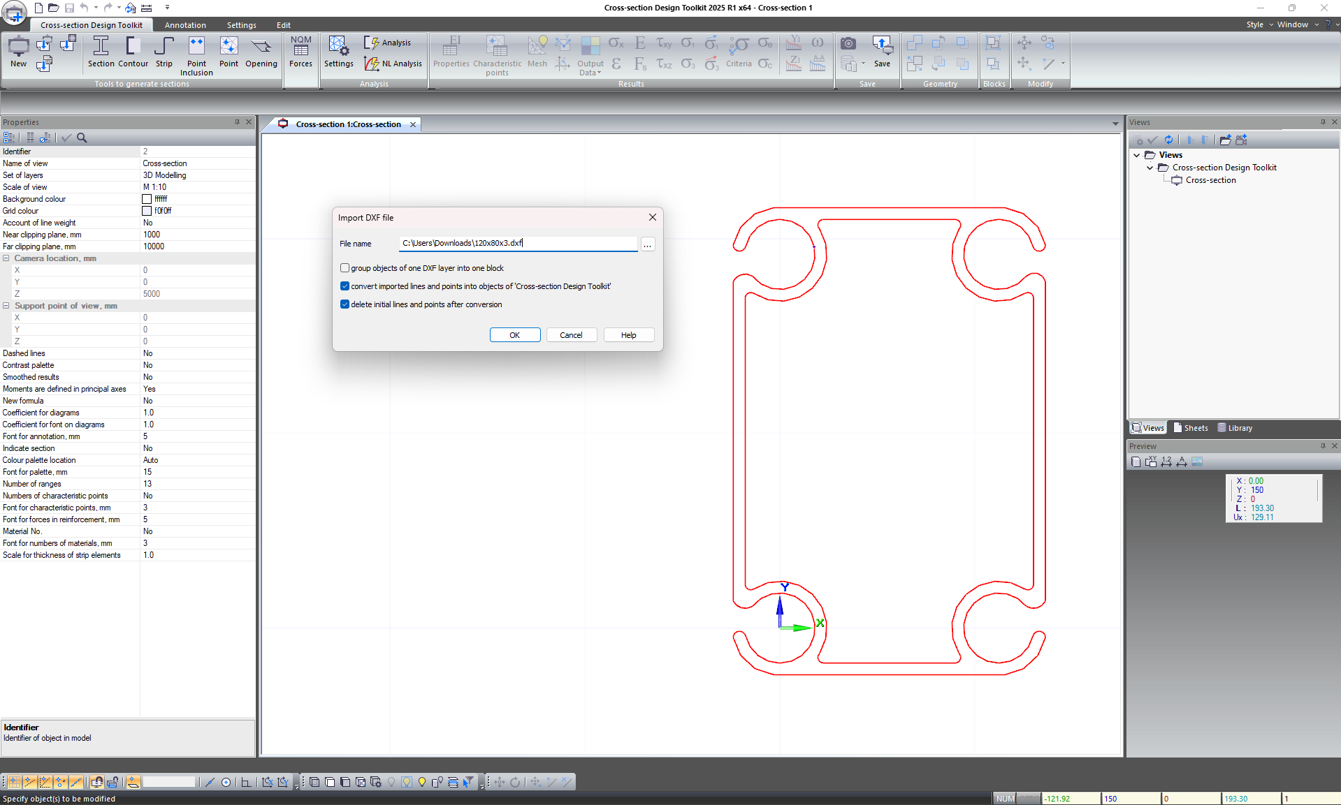
When the geometry is exported from *.dxf file, the arcs and segments that have matching ends in the *.dxf file are now included in the same contour.
Updated ‘Automatic Reinforcement’ tool with ‘Pattern’ option
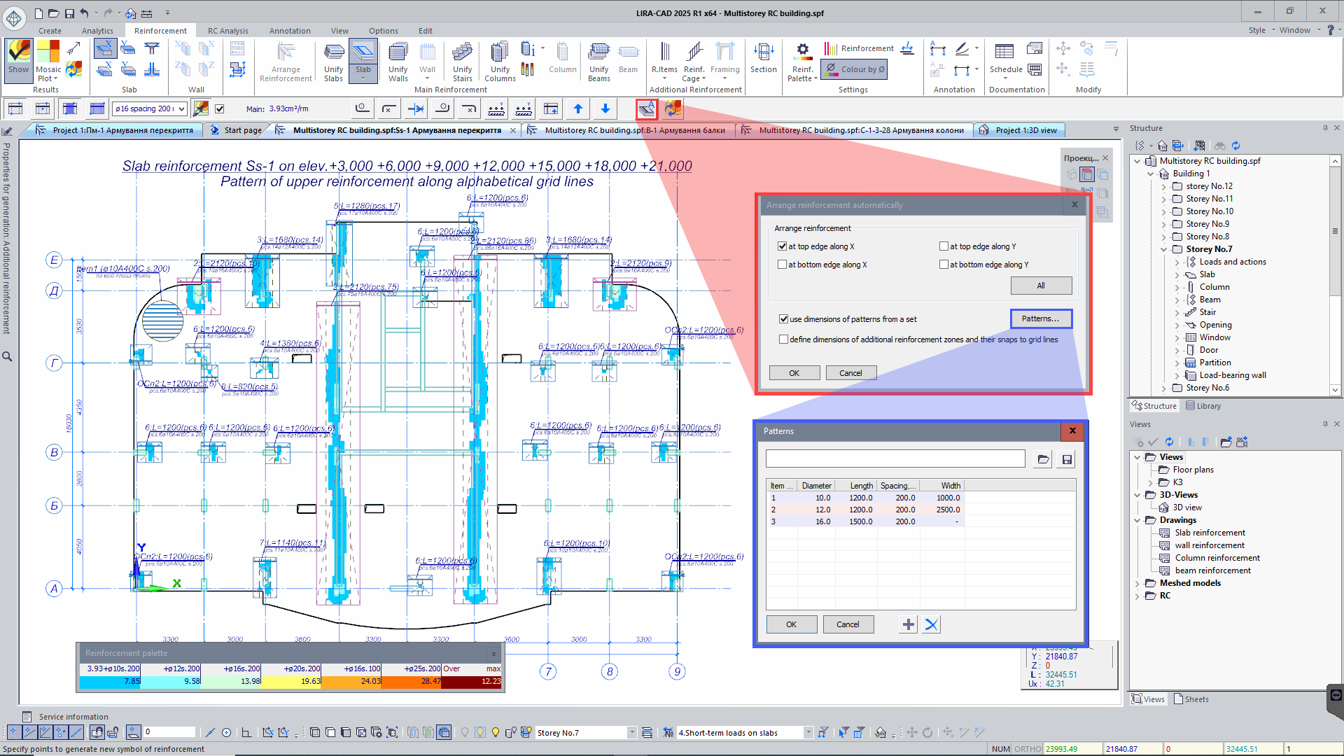
In the updated version of the Arrange reinforcement automatically tool, there is a new options - Patterns, which improves the process of generating the zones of additional reinforcement in floor slabs.
Tool Description:
In the Patterns dialog box, the user could manage a set of dimension-types for the additional reinforcement. Here it is possible to define the standard parameters that will be used for the automatic arrangement of reinforcement in the slab, taking into account the design and real values of reinforcement.
Configuration options:
- Rebar diameter
- Rebar spacing
- Grid dimensions (BxH)
The program takes into account that not every dimension-type set can perfectly meet all design requirements. Therefore, flexibility is maintained for correct adaptation to avoid errors due to inappropriate patterns. If the specified dimension-types meet the design situation, the program will give priority to these standard variants.
Benefits:
- Efficiency: The generation of reinforcement patterns for slabs speeds up because the suitable dimension-types are applied automatically.
- Save and reuse: Frequently used parameters of grids may be saved and applied to future projects, increasing productivity and convenience.
This tool ensures quick and precise arrangement of reinforcement by emphasising the use of diameters and dimensions relevant to the design situation.
Tool for detailed drawings of beam-to-column connection
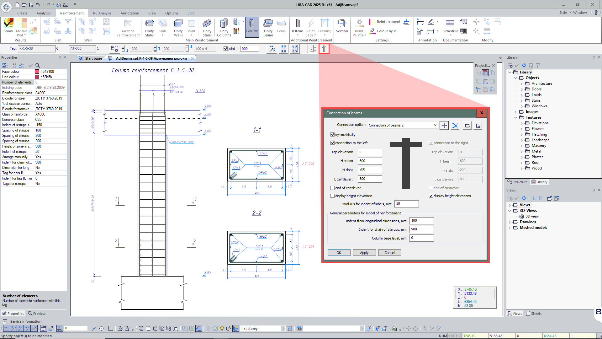
The tool for detailed generation of drawings for columns with adjacent beams (Beam-to-column connection dialog box). This tool allows the user to edit and customize parameters for the presentation of beam/slab-to-column connections on the drawing of reinforcement.
Key Functions:
Connections: In the dialog box it is possible to specify the elevations of the top edges of the adjacent elements, the thickness of the slabs and beams, and the dimensions of the cantilever part if there is no extension of horizontal elements. For symmetrical connections, select the appropriate check box to define the parameters and apply them to both sides.
Setting up a vertical cut:
- Customize the dimension lines to take account of adjacent beams and slabs to form a correct chain with vertical dimensions.
- Define indents for the dimensional chain of stirrups, longitudinal dimensions and column base elevations.
- To make design procedure easier, introduce a different method of labelling stirrups and longitudinal rebars.
Flexibility and efficiency:
All settings can be saved as a preset that will be applied to current or future projects. This significantly speeds up the generation of quality drawings with accurate parameters for connections, minimises errors, and optimises the work process. The tool increases the speed and provides the user-friendly workflow as the user could repeatedly apply pre-defined parameters, save time, and ensure high-quality design.
Documentation improvements
New option to define the format for numbers and fonts on graphs of time history analysis results (displacements, forces, loads on a fragment, loads on a group of partitions, nodal response spectrum).
New tables of results Heat flow by load cases are provided for problems with steady heat transfer analysis and transient heat transfer analysis.
New option to prepare documentation for interactive screen copies of design model for all new mosaic plots and graphs; expanded tables with the input data and analysis results.

Новости 41 - 49 of 49
First | Prev. | 1 2 3 | Next | Last