Dynamic masses, option to copy properties, assemblage stages, composite structures (steel & reinforced concrete), soil cushion (constructed soil), fire resistance analysis, piles, load combinations, output data in *.csv, ultimate inelastic strain, coupling of profiles, combined types of pilot reinforcement (PR types), rope, stability analysis, thin-walled shapes, driven piles, analysis of pilot reinforcement (PR), iterative solids
-
Plug-in for Tekla Structures: restored option to update the cross-sections according to results of FEA, selection/check of steel cross-sections.
-
Enhanced export from Revit to LIRA-SAPR: plates, openings and loads with curved contour segments.
-
Enhanced IFC import, namely:
-
import of wall snaps;
-
recognition of beam cross-sections;
-
recognition of column cross-sections;
-
fixed bug in recognition of the space elevation;
-
recognition of stairs and conversion of prisms into stairs is modified.
-
-
Fixed bug in IFC export that caused the application to fail in some cases.
-
Export from DWG is improved. When the "Section only" option is active for a section, stairs are no longer exported when exporting to DWG if they are not included in the section.
-
Enhanced option to copy storeys from one project to another.
-
Restored option to display the "Offset" parameter for beams in the "Properties" dialog box.
-
Enhanced algorithm for generation of punching shear contours for columns with a section rotated on plan.
-
Added check for the method of generation - "Rectangle". Now the object is not generated if two sides of the rectangle coincide.
-
Improved transfer of plates from VISOR-SAPR module to SAPFIR module (plates restored from the design model to physical model).
-
Account for the volume of capital and column base when calculating the concrete volume in columns.
-
Enhanced generation of bar analogues of partitions for walls with a large number of openings of different heights.
-
The "Fill pattern for opening" dialog box is modified.
-
Fixed bug in displaying reinforcement in 3D view.
-
Fixed bug: the load applied through the slab properties did not take into account the opening in slab.
-
Fixed bug: deleting the links between nodes in the algorithm saved to the SAPFIR library.
-
Enhanced work of GridWall node. Now triangulation is taken into account when the wall is copied by storeys.
-
Triangulation by nodes is improved.
-
Modified node for generation of grid lines from the underlay.
-
Modified nodes for import of IFC and XLS.
-
Fixed bug in nodes for load generation when load values should be obtained from tables via ImportXLS node.
-
Fixed bug in the ImportIFC node when trying to update it.
-
Fixed: possible bug when opening the *.lir files for problems that contain deleted but not packed elements in which dynamic masses were defined.
-
To copy the node properties, the "Copy for selected objects" command is restored in the "Information about node" dialog box.
-
Fixed a possible bug in solver; it occurred when the number of specified assemblage stages was large (more than 300 stages).
-
Fixed bug in transferring of SAPFIR models that contains composite (steel & reinforced concrete) cross-sections.
-
The calculation of bimoment Bw is clarified for the 3D bar with account of the warping of the section (FE type 7).
-
In the SOIL system, modified option to assign properties for the layer of soil cushion (constructed soil).
-
Corrected option to select transverse reinforcement in analysis on fire resistance for DBN B.2.6-98:2009.
-
In the calculation of pile stiffness, the pile parameter "exclude offset length from pile length" is corrected.
-
For FE 265, 266, the stiffness description is restored to output the correct value for a specified clearance.
-
When the DCL table is generated by SP RK EN 1990:2002+A1:2005/2011, the possible failure of the program is eliminated when creating the main combination that contains wind and snow types of loads.
-
Methods for importing files and generating the output data in CSV format are added to LIRA-FEM API.
-
Modified: option to account for ultimate inelastic strain when transferring DCF forces to the analysis of steel joints. Previously, the reduction factor was not taken into account when there were less than two components as a result of the earthquake analysis by KMK 2.01.03-19.
-
Fixed bug: failure of application when trying to configure coupling of built-up profiles of channel and channel+I-beam types.
-
Corrected: possible failure of the application when calculating parameters of nonlinear cracks in RC plates in which the reinforcement in the plate cross-section is defined using multi-component types of PR (pilot reinforcement).
-
The stiffness of the FE 310 and stiffness of the steel rope is now updated when diameter of the rope is modified.
-
Restored: stability analysis for thin-walled shapes (thickness less than 4 mm) by DBN B.2.6-198:2014.
-
Corrected: output of mosaic plots for utilization ratio in buckling of steel beams and columns.
-
Partial safety factor Yc is taken into account in calculating the load-bearing capacity of driven piles in pullout load.
-
For RC bars, correct presentation of values on the mosaic plot for reserve factor of reinforcement in the "Reserve factor/Additional reinforcement (RF/AR)" check mode, as well as the output of values in the "Reinforcement in elements" tables.
-
Clarified computation of the stress strain state in iterative nonlinear solids with the specified concrete and reinforcement.
-
For SP RK EN 1992-1-1:2004/2011, corrected the error in calculating the reserve factor for reinforcement in plate elements when the acting forces from shear loads are less than the load-bearing capacity of concrete section.
-
The restriction on the number of soil layers defined in the "Boreholes" dialog box of the SOIL system is removed.
-
Corrected documentation in the "Boreholes" input data table for the case when the numbering of boreholes does not start with "1".
Tekla Structures, Revit, import/export *.ifc, option to copy storeys, punching shear contours, volume of concrete, filling in thw opening, reinforcement, nodes, library, triangulation, grid lines
-
Plug-in for Tekla Structures: restored option to update the cross-sections according to results of FEA, selection/check of steel cross-sections.
-
Enhanced export from Revit to LIRA-SAPR: plates, openings and loads with curved contour segments.
-
Enhanced IFC import, namely:
-
import of wall snaps;
-
recognition of beam cross-sections;
-
recognition of column cross-sections;
-
fixed bug in recognition of the space elevation;
-
recognition of stairs and conversion of prisms into stairs is modified.
-
-
Fixed bug in IFC export that caused the application to fail in some cases.
-
Export from DWG is improved. When the "Section only" option is active for a section, stairs are no longer exported when exporting to DWG if they are not included in the section.
-
Enhanced option to copy storeys from one project to another.
-
Restored option to display the "Offset" parameter for beams in the "Properties" dialog box.
-
Enhanced algorithm for generation of punching shear contours for columns with a section rotated on plan.
-
Added check for the method of generation - "Rectangle". Now the object is not generated if two sides of the rectangle coincide.
-
Improved transfer of plates from VISOR-SAPR module to SAPFIR module (plates restored from the design model to physical model).
-
Account for the volume of capital and column base when calculating the concrete volume in columns.
-
Enhanced generation of bar analogues of partitions for walls with a large number of openings of different heights.
-
The "Fill pattern for opening" dialog box is modified.
-
Fixed bug in displaying reinforcement in 3D view.
-
Fixed bug: the load applied through the slab properties did not take into account the opening in slab.
-
Fixed bug: deleting the links between nodes in the algorithm saved to the SAPFIR library.
-
Enhanced work of GridWall node. Now triangulation is taken into account when the wall is copied by storeys.
-
Triangulation by nodes is improved.
-
Modified node for generation of grid lines from the underlay.
-
Modified nodes for import of IFC and XLS.
-
Fixed bug in nodes for load generation when load values should be obtained from tables via ImportXLS node.
-
Fixed bug in the ImportIFC node when trying to update it.
DCF, crane loads, tables, stiffness refinement, coupled DOF, soil properties, Report Book, surface load, super-elements, initial imperfections, modulus of dynamics 61, interface settings, step-type nonlinearity, input tables, METEOR system, steel, responsibility factors, brick piers, pile stiffness, progressive collapse, corrosion, Cross-section Design Toolkit, principal and equivalent stresses, Tekla Structures 2023, partial safety factors, SP RK EN 1998-1:2004/2012, 'fixed and non-fixed' elements, interactive tables, FOK-PC, nominal slenderness method.
- Fixed bug: snap of the section when mirror copying the columns.
- Fixed bug: behaviour of rebar dowels for columns with a shifted section (not in the centre of mass).
- Fixed option: creating storeys in the node Import
*.ifc. - Fixed bug: when importing curvilinear beams from
*.ifcfile. - Fixed bug: rotation of section for almost vertical beams.
- For inclined slabs, the option to create additional load cases in problems with assemblage analysis.
- Added option: to cut inclined columns by storeys.
- Fixed bug: in trim of beams for inclined columns.
- Fixed filter to export a 3D model to AutoCad.
- Fixed bug: in uniting slabs contours with holes.
- Restored option: to generate DCF combinations for crane loads.
- Fixed encoding in a number of text tables (in
*.rptformat): table of soil properties, results for calculation of subgrade moduli C1/C2, results of pile calculation, tables of results for analysis of metal structures. - Fixed bug: possible circularity during iterative stiffness refinement in the nonlinear structural analysis 'NL Engineering 1' for elements with a low percentage of reinforcement.
- Enhanced options to represent and modify groups with coupled DOF when number of groups is more than 10 000.
- Fixed bug: in displaying the text pasted from the Clipboard in the 'Soil properties' dialog box.
- Fixed bug: in restoring elements of the Report Book with names that contain Cyrillic characters.
- For mosaic plots of concentrated loads, new option to visualize separately the surface loads and other concentrated forces.
- Fixed bug: in the presentation of DCF results for super-elements whose names contain Cyrillic characters.
- For finite elements included in a structural element, duplication of loads is eliminated when specifying initial imperfections.
- For the earthquake load by SP RK EN 1998-1:2004/2012, NTP RK 08-01.1-2021 (dynamics module 61), corrected visual representation for the graphs of the horizontal and vertical dynamic factors for the III-rd type of soil.
- Fixed bug: in transferring the settings for user interface from previous versions of LIRA-FEM program.
- For nonlinear problems with super-elements, enhanced presentation of results at intermediate steps of nonlinear histories; and for super-elements presented in full, enhanced presentation of results in the window with information about nodes and elements.
- For the step-type nonlinear problems, restored text tables of forces by DCL at the final steps of nonlinear load histories.
- Fixed bug: in copying the 'Design combinations of loads (DCL)' input table to another design model.
- Fixed bug: possible failure of the program when you make a mirror copy of the model fragment.
- Enhanced option: arrangement of stiffeners in a universal bar of variable cross-section.
- Fixed bug: in saving a group of images in folders with long names (Report Book).
- In the METEOR system, restored option to generate an integrated problem in the 'DCF+' mode for problems with time history analysis and problems with nonlinear load histories.
- Improved scaling of toolbar icons for 4K UHD monitors.
- Added option: account for user-defined values of structure responsibility coefficients when calculating DCF for brick piers.
- In calculation of pile stiffness, enhanced options to define the type of soil layer under the pile toe.
- Fixed bug: in computing the width of settlement zone for some types of standard sections.
- In analysis of steel structures on progressive collapse, in history/DCF/DCL for the last load case (Special/Emergency), it is possible to define the duration coefficient to check by deflections.
- Fixed bug: possible pause of batch analysis during iterative refinement of pile stiffness.
- Fixed bug: possible discrepancy between values in dialog boxes and in the report file when displaying the results for the calculation of forces in partitions.
- For steel sections analysed with account of corrosion, refined values for utilization ratio (in case of overall stability) that are displayed in the result file.
- Fixed bug: when exporting shear forces to the 'Cross-section Design Toolkit' module.
- Fixed bug: in displaying the results of calculating the principal and equivalent stresses by DCF in large problems (more than 32 thousand elements).
- Added plug-in for integration with Tekla Structures 2023.
- Fixed bug: in analysis of reinforced concrete elements on shear force, for groups of forces A1, B1, C1, D1, E1, corrected use of coefficients yb2 and yb3.
- In analysis of reinforced concrete elements on shear force according to SP RK EN 1998-1:2004/2012, enhanced generation for design parameters of materials.
- In analysis of reinforced concrete bars according to SP RK EN 1998-1:2004/2012, corrected influence of the parameter 'fixed/non-fixed' element in analysis by nominal slenderness.
- Fixed bug: in encoding the
*.xlsfiles for interactive tables with results. - Fixed bug: in export of data (for calculation of foundations) from LIRA-SAPR 2022 to FOK Complex in the case the export file contained Cyrillic characters.
- Fixed bug: in rotating the model about the global X and Y axes when the design model (in isometric projection) is rotated.
- In analysis of reinforced concrete bars according to SP RK EN 1998-1:2004/2012 for columns, enhanced calculation of the reduced moments in analysis by nominal slenderness.
*.ifc import, snap of section, rebar dowels, nodes, curvilinear beams, inclined slabs, trim option for beams.
- Fixed bug: snap of the section when mirror copying the columns.
- Fixed bug: behaviour of rebar dowels for columns with a shifted section (not in the centre of mass).
- Fixed option: creating storeys in the node Import
*.ifc. - Fixed bug: when importing curvilinear beams from
*.ifcfile. - Fixed bug: rotation of section for almost vertical beams.
- For inclined slabs, the option to create additional load cases in problems with assemblage analysis.
- Added option: to cut inclined columns by storeys.
- Fixed bug: in trim of beams for inclined columns.
- Fixed filter to export a 3D model to AutoCad.
- Fixed bug: in uniting slabs contours with holes.
assemblage stages, additional load cases, max area of reinforcement, test perimeter, surface load, PRB, coefficient to modulus of elasticity, behaviour coefficient, DCL, graph of change in reactions over time, deformed shape, structural blocks, summing up loads, polar moments of inertia for masses, partitions, damping ratio, earthquake combination, input tables, load case editor, dynamic load cases, post-stage load cases, iterative process, analysis by accelerogram, foundations for machine with dynamic loads, horizontal stiffness, load combinations, properties of GE, soil cushion, piles, punching shear analysis, slenderness ratio, pattern of crack propagation, effective length, buckling, time history analysis, shear stress, steel grades, bore holes, wind loads, asymmetric pressure, summing up mode shapes, project structure, new triangulation method, joints, embedded items, drawings, reinforcement pattern, transverse reinforcement, reinforcing cages, nodes
Interoperability - components of BIM technology
-
Improved plug-in Revit - LIRA-SAPR:
- the 'Export' dialog box is now non-modal, so it is possible you to assign properties to Revit analytical models without closing the dialog box;
- restored option to export the Linear load to the element from Revit 2022 to LIRA-FEM program;
- new option to assign 'materials by category' for the English localization of the program.
-
Combined
*.dwgand*.dxfimports for the 'Import floor plans', 'Import AutoCad drawing', 'Import model to new project' commands and for the 'Import underlay in*.dxf,*.dwgformat' node. - In the 'Import floor plans' dialogue box, the storey height may be saved to the parameter template to be applied later.
-
Enhanced import of IFC:
- storeys are created by slabs for models that are saved in the IFC as one storey;
- improved recognition of walls with a large number of faces;
- improved recognition of openings;
- new recognition of object colours;
- improved import of beams.
SAPFIR-Structures
- If the wind load is applied by method '1 - to ends of floor slabs', the pressure/suction option is implemented separately (for all building codes). If the option is defined as 'Yes', then the separate loads are generated for the positive and negative wind pressure.
- SP RK EN 1991-1-4:2005/2011 Wind loads, clause 7.1.2 (Asymmetric wind pressure) is supported. If the wind load is applied by method '1 - to ends of floor slabs' and '2 - positive/negative wind pressure', it is possible to define the parameter 'Asymmetric wind pressure' with pressure coefficients (left/right) for all building codes.

- In the 'Sum up loads' dialog box, there is new option to edit the total load separately for each direction and for each load case. This option is available in the 'Architecture' and the 'Meshed model' modes.
- New modules for earthquake loads according to building codes of Uzbekistan KMK 2.01.03-19 (module 33), Tajikistan MKS CHT 22-07-2007 (module 48) and Georgia PN 01.01.-09 (module 53).
- The following parameters are added for all earthquake modules:
- the required percentage of modal masses;
- option to sum up the displacements with the same frequency;
- option to define the method for summing up the earthquake components;
- account of excluded and non-computed mode shapes.
- In the 'Meshed model' mode, the 'Copy loads to architecture' option is available in the 'Load cases' dialog box, on the 'Edit load cases' tab (see the shortcut menu). It enables the user to copy any loads to architecture, including wind loads and loads obtained after the load collection with proxy objects.

-
Option to delete the load case together with all loads it contains:
- for wind, earthquake, special load and soil pressure - the relevant items are deleted in the 'Structure' window;
- for the load defined in the properties of slab - the relevant item with the load value becomes clear;
- for objects with interpretation 'Load' (partition, beam, column, slab, etc.) - the object itself is deleted.
- A new triangulation method 'adaptive quadrilateral version 2' is implemented. Based on comparison results, for certain problems, the 'adaptive quadrilateral version 2' method may speed up the process by 2 to 4 times. The greater the ratio of model dimension to triangulation step and the more mandatory points for triangulation, the faster the triangulation will be with the new method relative to the previous method. Also for a number of problems in which the 'Smooth mesh' option enabled, the FE mesh quality is considerably enhanced.
 and adaptive quadrilateral version 2 with smoothing (right).png")
Large Panel Buildings
- Enhanced division of the FE of joint over openings.
- Enhanced generation of embedded items in the joint over the openings in case the 'Lintel is simulated with bar' option is defined in the properties of the opening.
Design of RC structures (Reinforced Concrete)
- The drawings and detail views for punching shear according to the SP RK EN 1992-1-1:2004/201.
- A new 'Arrangement of reinforcement' dialog box is mentioned to define the parameters for the arrangement of transverse reinforcing bars in punching shear and then to design with separate rebars or reinforcing cages.

Generator
- Added nodes: 'Arc by three points', 'Arc by two points and direction', 'Plane by three points'.

VISOR-SAPR
- For EN 1990:2002+A1:2005, SP RK EN 1990:2002+A1/2011, it is possible to generate characteristic DCL(c) from the output data for time history analysis of the problem. With this option you could, for example, use the time history analyses for the design of active seismic insulation and at the same time to verify the load-bearing capacity of structural elements (reinforced concrete, steel).
 for problems with time history analysis.png")
- Enhanced visualization of the model so that assemblage stages are displayed with account of additional load cases. When this option is enabled, not only the elements assembled at this stage are displayed, but also the additional load cases associated with this stage. Mosaic plots for loads and summing up the loads (additional load cases defined in the current assemblage stage are considered) will depend on whether this option is enabled or not.

-
For problems in which erection is modelled, new checks for the input data are added. In the 'Model nonlinear load cases' dialog box, there is new command to select the elements assembled (mounted) at the current stage with loads applied before assemblage.
-
New option to add the selected element to the list of elements that should be assembled or disassembled.
-
New option to display the mosaic plot for max area of longitudinal reinforcement at the corners/top and bottom faces/side faces of the bar section along the certain direction.

-
New mosaic plots for the output data from analysis of reinforced concrete (RC) structures:
-
codes for errors in calculation of seismic safety factors FS in bars and plates for DBN B.2.6-98:2009 'Concrete and reinforced concrete structures';
-
test perimeter Uout in punching shear according to SP RK EN 1992-1-1:2004/2011 'Design of reinforced concrete structures'.
-
-
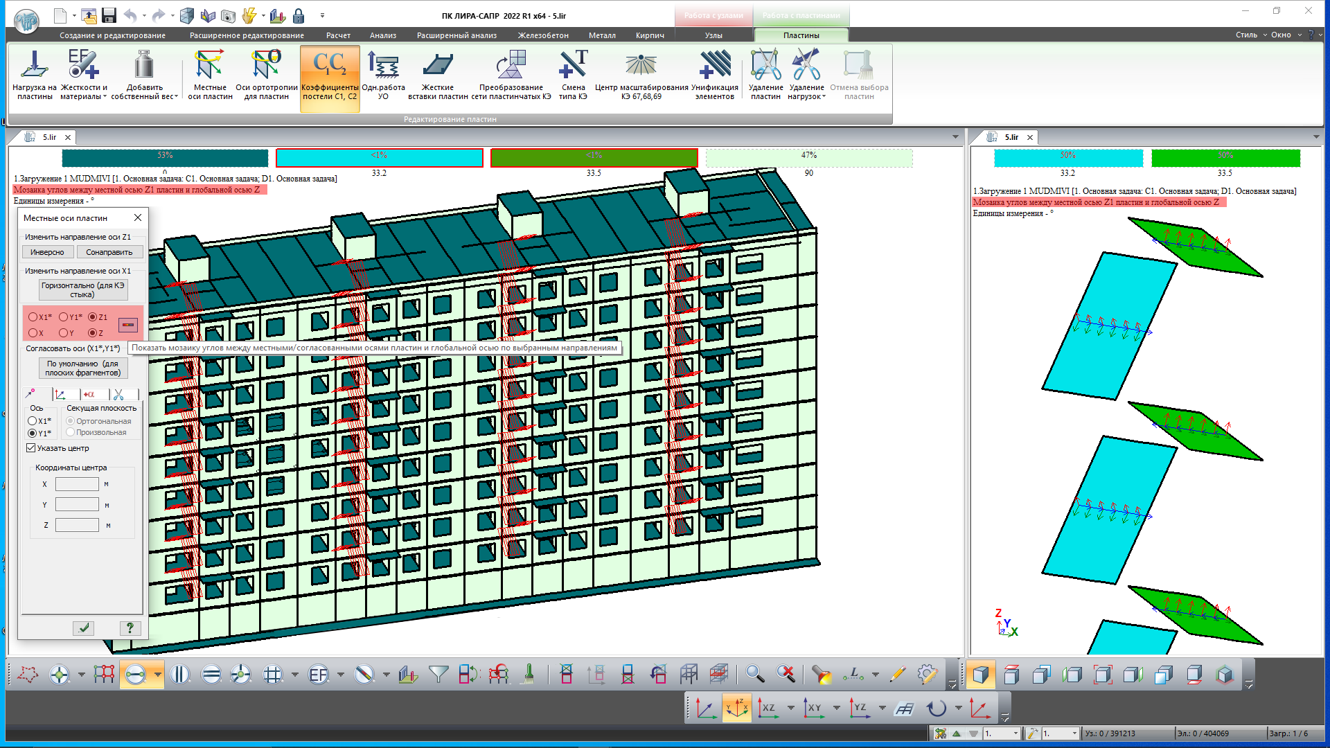
Mosaic plots for angles between the selected local (unified) axis/axis of orthotropy of the plate and the global axis.

-
New option to edit the surface loads in groups.
-
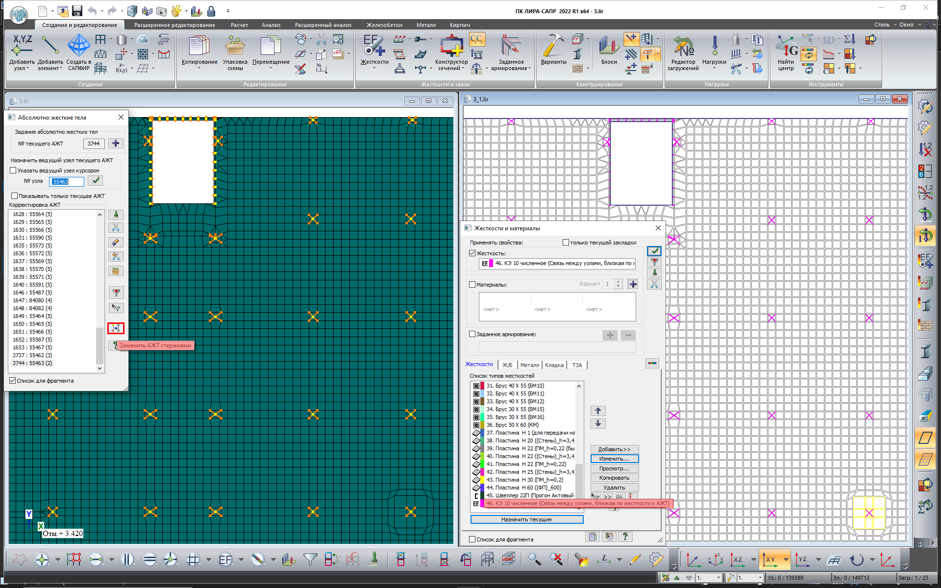
When perfectly rigid body (PRB) is generated, there is an option to convert selected PRB into bars of high stiffeness. This feature may be helpful when modelling thermal loads, e.g. for floor slabs to avoid stress concentrations at the slab-to-column connections.

-
Visualization of envelopes for max, min and max in absolute value of the examined parameter for nonlinear histories (without intermediate results) and crack parameters (with intermediate results).
-
Visualization of envelopes for max in absolute value (ABS) examined parameters for DCF and DCL characteristic.

-
When the coefficient for modulus of elasticity is defined, there is a new option to edit the coefficients (defined earlier) for the selected elements or for the whole model by a factor of n times.
-
In the 'Skews' dialog box, new behaviour coefficient q is added to calculate the sensitivity coefficient of storey skew in the earthquake design situation.
-
In the 'Design combination of loads' dialog box, there is a new option 'Replace types of load cases in the current DCL table with the data from the 'Edit load cases' dialog box'.
Important: When this command is activated, the DCL combinations defined earlier will be reset.
-
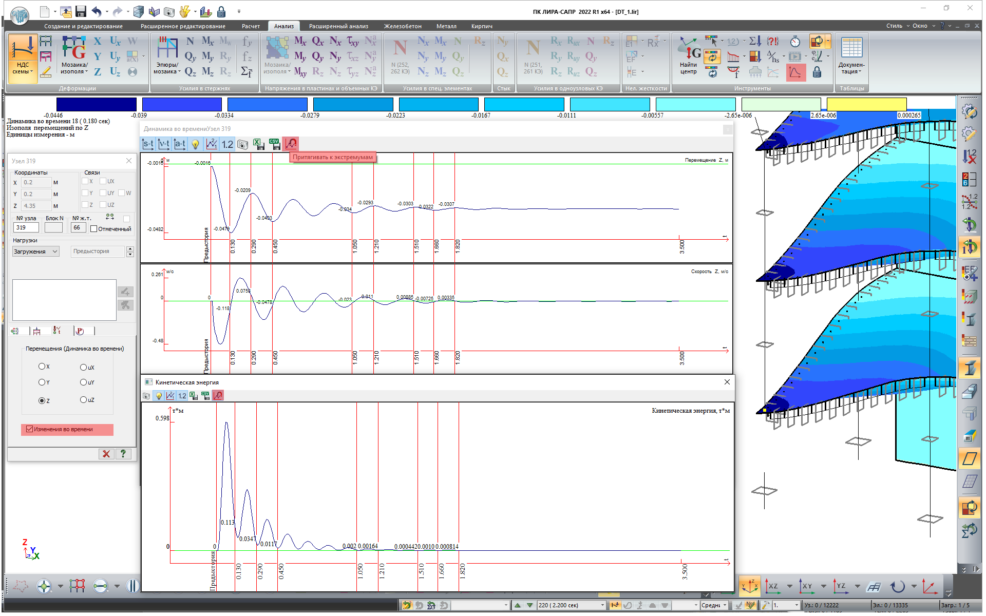
In time history analysis, the changes in reactions over time can be displayed graphically for the nodes where the load (reaction) on the fragment is calculated.

-
In the window with graphs for changes over the time, new command 'Bring to extreme values': displacements, forces, loads on a fragment, loads on a group of partitions, temperature and graphs of kinetic energy. When the 'Bring to extreme values' mode is activated and you add the check time points with the mouse pointer, the time point with the nearest local extremum will be assigned.

-
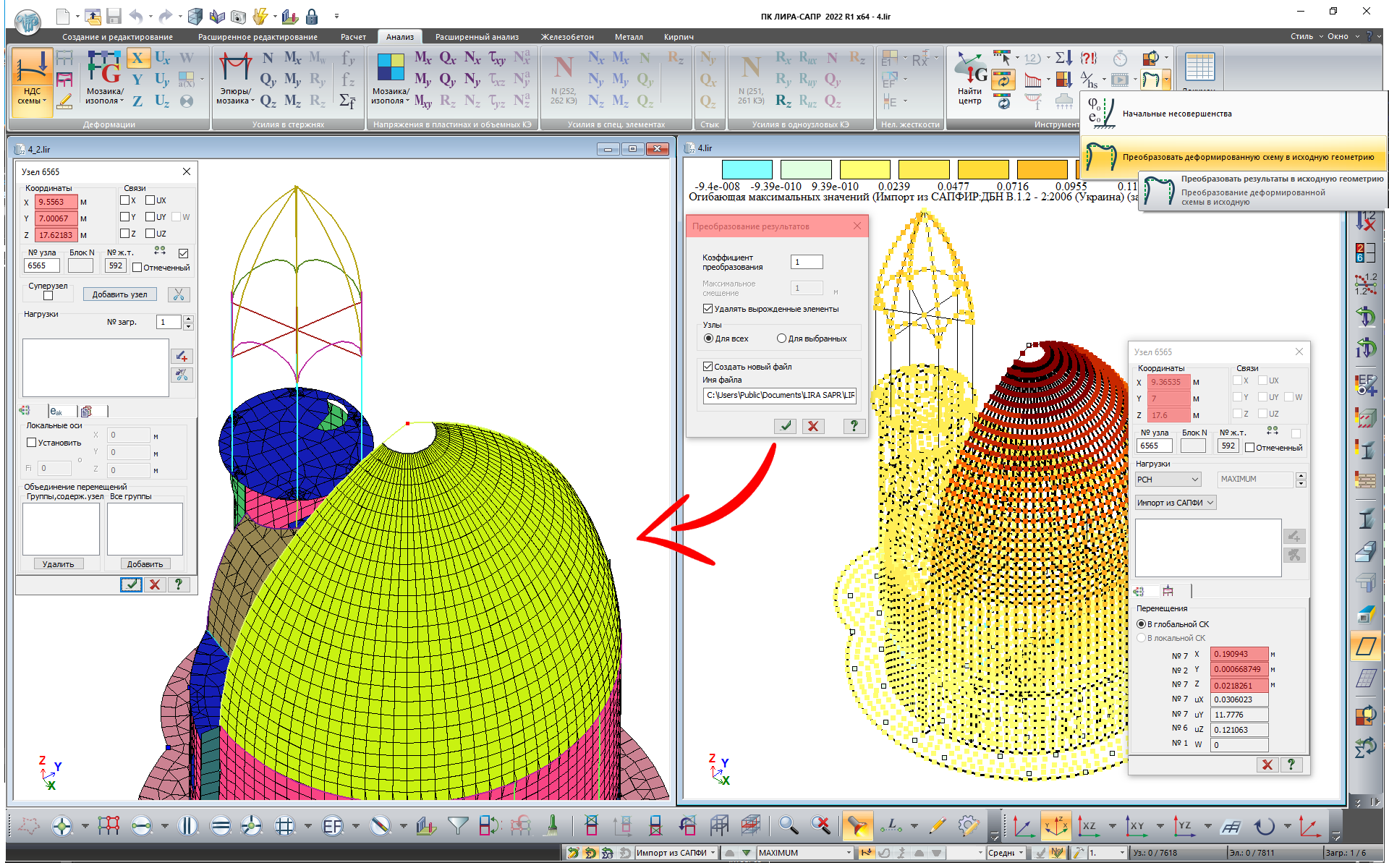
To consider the imperfections in complex structures, the strategy is to generate the initial geometry with curvature. A better selection of shape for the initial imperfections should replicate the global buckling mode. The current version implements a technology to update the model's geometry according to the results (displacements, mode shapes, buckling mode).

-
Option to convert the soil pressure into a static load.

-
Option to define the side for presentation of grid line tags.

-
Option to automatically subdivide (along the vertical) the structural blocks of walls and columns with account of defined elevations.
 with account of defined elevations.png")
-
In the 'Summarize loads' dialog box, new option to calculate polar moments of inertia of masses both for the whole model and for an arbitrary fragment of the model relative to the calculated centres of masses or arbitrarily defined poles.

-
Option to recalculate the total and unit loads calculated on partitions (for cases when the group of partitions and/or design levels is modified after complete analysis).
-
Option to assign the damping ratio to elements of the design model and to visualize the mosaic plot for damping ratio.
By default, damping ratio for the elements are not defined (=0). It is possible to assign different damping ratio to certain elements. If the damping ratio is not assigned to some elements, then the value of the damping ratio defined in parameters for dynamic modules 27 and 29 will be applied in analysis.

-
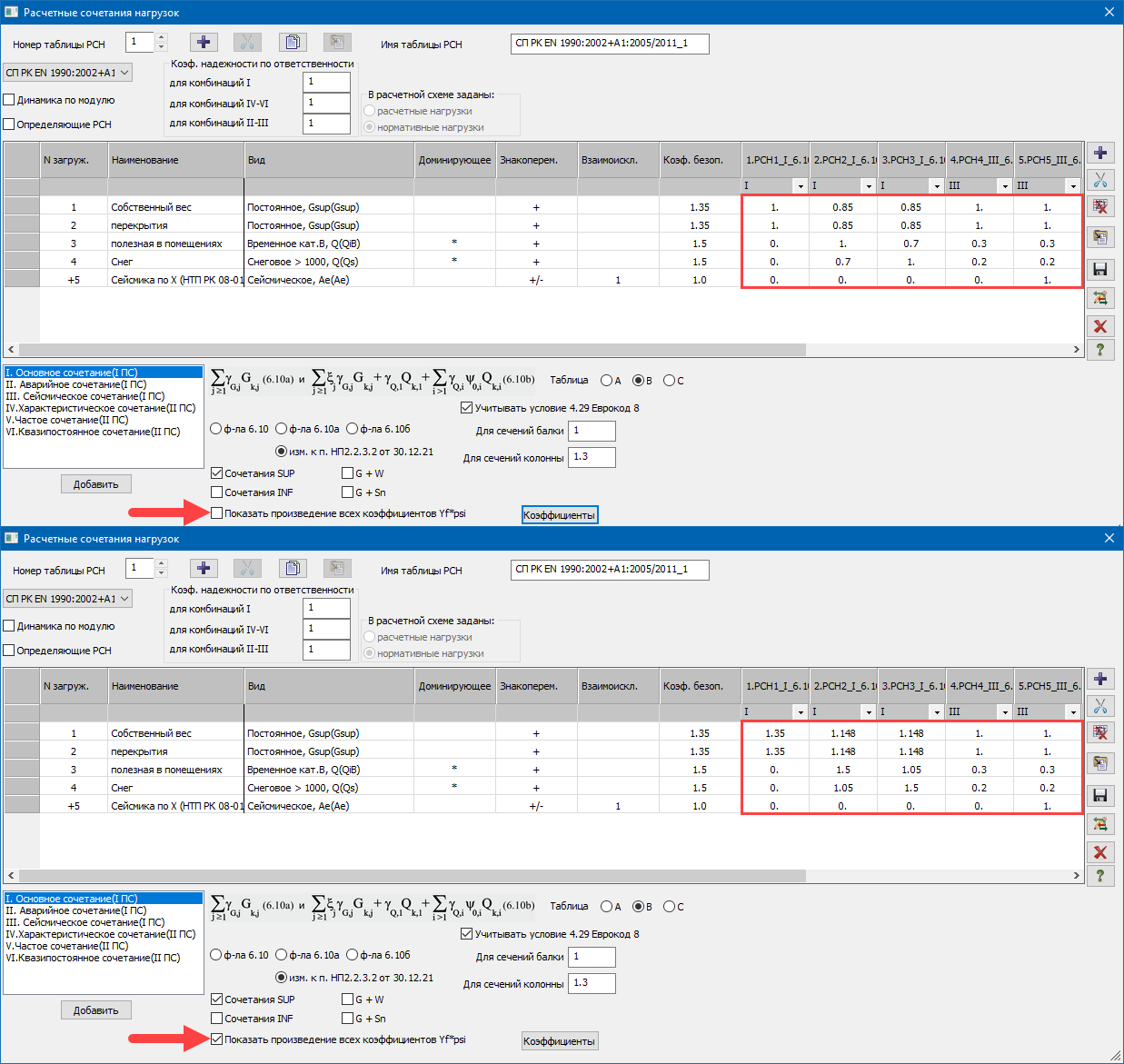
For SP RK EN 1990:2002+A1:2005/2011, the option to present the combination table 'explicitly', so the combination coefficients and reduction factors are corrected with account of the safety factors to the loads and the type of defined loads.
Important. In the current release, this option is implemented for the case when the normative loads are used in the model.

-
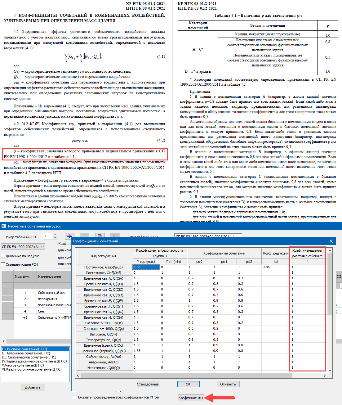
In the DCL table for the SP RK EN 1990:2002+A1:2005/2011, in the 'Coefficients' dialog box, new column with fi coefficients that reduce the contribution of the load case to the earthquake design combination. By default, all values are 1.
Note: According to the new NTP RK 08-01.2-2021 (see pages 43-45, chapter 4), it is necessary to reduce the contribution of some temporary loads to the generation of masses for earthquake load. Coefficients of combinations in the respective load types will be multiplied by the specified reduction coefficients fi. It is recommended to create a separate DCL table specifically to generate earthquake masses. The fi coefficients should be modified there and a DCL combination should be generated; the masses will be collected from this combination.

-
An input table for 'Coefficients to stiffness' related to subproblems.
-
An option to control the generation of a tracing routine for the punching shear analysis of a certain contours by SP RK EN 1992-1-1:2004/2011 'Design of reinforced concrete structures'.

-
The high speed of DCL calculations is restored.
-
Enhanced generation of mosaic plots for the concentrated loads. Surface loads specified for plates and solids now are not considered in mosaic plots for the concentrated loads.
-
The data in the dialog boxes 'Edit load cases', 'Table of dynamic load cases' and 'Account of static load cases' is synchronized.
-
For 'collapsed' dynamic load cases, in the mode of analysis results' visualization, a table of coefficients may be pasted from the Clipboard. By default, the coefficients for the components will remain '1' in this case.
-
New commands on the ribbon user interface, new menus and toolbars in the classic user interface.
-
Numerous interface and other user requests are implemented.
FEM solver
-
Coefficient to stiffness (kE) may be applied to all nonlinear elements available in the analysis of post-stage load cases. So, the coefficients are applied to the linearised stiffnesses obtained in the analysis by 'NL Engineering 2'. This feature may be helpful, for example, when it is necessary (1) to use the diagrams for materials’ behaviour in long-term load, (2) to redistribute stiffnesses with account of cracks in RC sections and (3) for post-stage load cases (wind pulsation, impact/harmonic, earthquake), to transfer to the short-term modulus of elasticity.
-
For each dynamic load with specific criteria for termination of the iterative process (reaching the required number of total modal masses, ultimate frequency, etc.), after each iteration the program displays information about the accumulated total masses (for earthquake) and about the max calculated frequency (for pulsation components). According to this information the user could evaluate whether the iteration process should be continued or terminated to reduce the time for analysis.
-
In the analysis by the accelerograms with dynamics modules 27 and 29 for design models that consist of elements or fragments of structures with different damping properties, the analysis of equivalent damping for the j-th eigenvalue of vibrations is implemented according to the following formula: ξj={φj}T*∑[ξK]i*{φj}/{φj}T*[K]*{φj}
where {φj} is the vector of the j-th mode shape, [K] is the stiffness matrix for the model, ∑[ξK]i is the stiffness matrix for the i-th element or fragment of the structure multiplied by the damping ratio for that element.
SOIL
-
Calculation of elastic foundation ('Method 5') by formula (4) SNIP 2.02.05-87 'Foundations of machines with dynamic loads'. It enables the user to compute the coefficient of elastic uniform compression Cz (C1z) in dynamic loads on the foundation.
-
Stiffnes for one-node FE is calculated in order to simulate the shear stiffness of the soil base depending on the C1z assigned to the adjacent elements or on the C1z defined by the user.
Note: It is possible to calculate the stiffness of a one-node FE that simulates the rotational stiffness of the soil base around the vertical and horizontal axes. It should be noted that the linear stiffnesses distributed at the foundation base – subgrade moduli C1=Cz - also resist the rotation of the building. Therefore, the obtained rotational stiffnesses distributed across the foundation area on the one-node FEs at the appropriate nodes, should be modified by the user.
Tip: To introduce elastic springs in foundations, it is preferable to use FE57 rather than FE51, as in this case no extra stiffnesses will appear in the list of stiffness. In this case, to obtain mosaic plot of stiffness in FE57 for the visualization and the report, use the drop-down menu 'Mosaic plots of geometric properties of piles'.

-
New option to combine loads not only by %, but also by min absolute value. A global setting is added to the 'Options' menu.
-
Option to numerically display the properties of the geological element (GE) on the soil profile. This graphical representation may be used for documentation in the Report Book.
-
Direction of the local Z1-axes of horizontal plates is examined to exclude the positive soil pressure Rz. It is required so that the positive soil pressure Rz is not transferred to the input data in case C1/C2 is calculated iteratively.
-
Expanded options to define the soil cushion:
- to generate a soil cushion of variable layer depth - 'Up to the bottom of the layer';
- to add the weight of the soil cushion to the additional loads (in this case, the natural pressure is considered only from the natural soil).

Notes:
In the first release of version 2022, there was new option to define parameters of the soil cushion for individual subgroups of imported loads. Now the whole set of new parameters may be also applied separately for different foundation fragments that the separate Pz subgroups are assigned to.
In LIRA-SAPR 2022 R1 and earlier versions, the soil cushion was considered as part of the natural soil. In this case, the diagram of natural pressure was generated from heavier soils (natural soils or soil cushion in order to calculate a more conservative result - a greater depth of compressible stratum). But the diagram from the weight of excavated soil (sigma-zy) is in all cases generated only from the natural soils. The important point is that for the soil cushion, the conversion factor to the 2nd modulus of elasticity should be defined as equal to 1, because the soil cushion is not deformed by the natural pressure of the natural soil.
From LIRA-SAPR 2022 R2, it is possible to automatically generate the weight of the soil cushion and add it to the additional loads (including soil cushion of variable layer depth). So the soil cushion may be considered as part of the foundation and not the ground (so for this case the natural pressure is only considered from the natural soil).
The figure below considers a two-level foundation in which the natural soil is automatically replaced. In this case:
for the lower foundation, the soil cushion is defined as part of the natural soil (does not generate additional pressure - e.g. weak soil is replaced on the construction site, settlement from the weight of the soil cushion is complete, and then the foundation and basement structures are erected);
for the upper foundation, the soil cushion that replaces the weak soil is already a part of the foundation, as its weight affects the settlement of the available parts of the foundation and the plinth.
 Diagrams of the natural and additional pressure when the soil cushion is a part of the natural soil (Soil_cushion-no_weight)
 Diagrams of the natural and additional pressure when the soil cushion is a part of foundation (Soil_cushion-with_weight)
-
It is now possible to exclude the length of the offset from the pile length. Thus, the pile length from the bottom edge of the foundation slab to the pile toe can be specified in the input data.
ARM-SAPR (Reinforced Concrete Structures)
-
Option to check and select reinforcement based on the DCL(c) generated for problems with time history analysis.
-
For the SP RK EN 1992-1-1:2004/2011, the force combinations are divided into groups (fundamental, emergency and earthquake); the corresponding material properties are considered in the punching shear analysis.
-
For structural elements of columns where reinforcement is selected for flexibility by nominal curvature, a single output is available for the results of the selected areas for all elements in the structural element. This option is available for analysis according to SP RK EN 1992-1-1:2004/2011.
-
For SNIP 2.03.01-84*, in the material parameters 'Concrete', there is a new option 'Clarify the pattern of crack propagation'. When this option is active, analysis of longitudinal reinforcement for a plate element will be carried out regardless of the ratio of the core moment tensor and the crack propagation moment.
-
The calculation of the effective length factor for structural elements is corrected for SP RK EN 1992-1-1:2004/2011. In earlier versions, moments for calculating Meqv. were taken at the ends of the StE, but the effective length factor was taken from the lengths of the individual StE.
-
Output of results in case the 'Reinforcement was added according to strength in inclined sections'.
-
Modified algorithm for analysis of reinforcement in plate elements according to Karpenko's theory in buckling.
STC-SAPR (Steel Structures)
-
DBN B.2.6-198:2014 Amendment No. 1 is supported.
-
New check/selection of the section by the DCL(c) generated for problems with time history analysis.
-
In the local mode, for the element type 'column', a separate output of utilization ratio % is provided for tangential stresses. In previous versions, the results of this check were included in the final utilization ratio, so it was difficult to evaluate the analysis results.
SRS-SAPR (Steel Tables)
- New steel tables are added:
- DSTU 8539:2015 'Rolled steel for building steel structures';
- DSTU 8541:2015 'High-strength rolled steel products';
- DSTU 8938:2019 'Seamless hot-deformed steel pipes'.
BRICK (Masonry Structures)
-
In problems with time history analysis, it is possible to generate the graph for change in loads for brickwork levels.

Report Book (Documentation system)
-
If a group of selected Report Book images is saved simultaneously and the 'Apply to all files' checkbox is selected, there is new option to resize the remaining images by enlarging or reducing the first image for which dimensions are shown in the corresponding boxes.

-
To control and document the input data, there is new option to present the DCL combinations with formula.

- New option to document soil and borehole properties and paginate this data.
- Option to save the graphs of changes in reactions over time in *.xls, *.csv format.
- A column with an index of a force group is added in the table of forces in the punching shear analysis.
Interoperability - components of BIM technology
-
Improved plug-in Revit - LIRA-SAPR:
- the 'Export' dialog box is now non-modal, so it is possible you to assign properties to Revit analytical models without closing the dialog box;
- restored option to export the Linear load to the element from Revit 2022 to LIRA-FEM program;
- new option to assign 'materials by category' for the English localization of the program.
-
Combined
*.dwgand*.dxfimports for the 'Import floor plans', 'Import AutoCad drawing', 'Import model to new project' commands and for the 'Import underlay in*.dxf,*.dwgformat' node. - In the 'Import floor plans' dialogue box, the storey height may be saved to the parameter template to be applied later.
-
Enhanced import of IFC:
- storeys are created by slabs for models that are saved in the IFC as one storey;
- improved recognition of walls with a large number of faces;
- improved recognition of openings;
- new recognition of object colours;
- improved import of beams.
SAPFIR-Structures
- If the wind load is applied by method '1 - to ends of floor slabs', the pressure/suction option is implemented separately (for all building codes). If the option is defined as 'Yes', then the separate loads are generated for the positive and negative wind pressure.
- SP RK EN 1991-1-4:2005/2011 Wind loads, clause 7.1.2 (Asymmetric wind pressure) is supported. If the wind load is applied by method '1 - to ends of floor slabs' and '2 - positive/negative wind pressure', it is possible to define the parameter 'Asymmetric wind pressure' with pressure coefficients (left/right) for all building codes.
- In the 'Sum up loads' dialog box, there is new option to edit the total load separately for each direction and for each load case. This option is available in the 'Architecture' and the 'Meshed model' modes.
- New modules for earthquake loads according to building codes of Uzbekistan KMK 2.01.03-19 (module 33), Tajikistan MKS CHT 22-07-2007 (module 48) and Georgia PN 01.01.-09 (module 53).
- The following parameters are added for all earthquake modules:
- the required percentage of modal masses;
- option to sum up the displacements with the same frequency;
- option to define the method for summing up the earthquake components;
- account of excluded and non-computed mode shapes.
- In the 'Meshed model' mode, the 'Copy loads to architecture' option is available in the 'Load cases' dialog box, on the 'Edit load cases' tab (see the shortcut menu). It enables the user to copy any loads to architecture, including wind loads and loads obtained after the load collection with proxy objects.
-
Option to delete the load case together with all loads it contains:
- for wind, earthquake, special load and soil pressure - the relevant items are deleted in the 'Structure' window;
- for the load defined in the properties of slab - the relevant item with the load value becomes clear;
- for objects with interpretation 'Load' (partition, beam, column, slab, etc.) - the object itself is deleted.
- A new triangulation method 'adaptive quadrilateral version 2' is implemented. Based on comparison results, for certain problems, the 'adaptive quadrilateral version 2' method may speed up the process by 2 to 4 times. The greater the ratio of model dimension to triangulation step and the more mandatory points for triangulation, the faster the triangulation will be with the new method relative to the previous method. Also for a number of problems in which the 'Smooth mesh' option enabled, the FE mesh quality is considerably enhanced.
Large Panel Buildings
- Enhanced division of the FE of joint over openings.
- Enhanced generation of embedded items in the joint over the openings in case the 'Lintel is simulated with bar' option is defined in the properties of the opening.
Design of RC structures (Reinforced Concrete)
- The drawings and detail views for punching shear according to the SP RK EN 1992-1-1:2004/201.
- A new 'Arrangement of reinforcement' dialog box is mentioned to define the parameters for the arrangement of transverse reinforcing bars in punching shear and then to design with separate rebars or reinforcing cages.
Generator
- Added nodes: 'Arc by three points', 'Arc by two points and direction', 'Plane by three points'.
Slab contours, axes, *. ifc, Autodesk Revit, load collection, special load, intersections, steel table, pile array, levels, PRB, lintels, joint, reinforcement colour palette, rope, SP RK EN 1992-1-1:2004/2011, SP RK EN 1993-1-1:2005/2011, DCF table, characteristic combination, modal analysis, three-component accelerogram, metal section, moduli of subgrade reaction (subgrade moduli), analysis on seismogram, analysis termination, trapezoidal load, loading by formula, structural elements, calculation of deflection
Interoperability
-
For floor plans, corrected bugs in case:
- two slab contours (foundation slabs) are generated if one of their edges coincides;
- grid lines are created by layer if the grid line label and grid line itself are on different layers.
- Enhanced export of beams to IFC file.
- Fixed bug in the output for results of reinforcement for the LIRA-FEM and Autodesk Revit integration.
Preprocessor LIRA-CAD
- For the 'Special load' tool, the number of created loads is displayed in the 'Edit load cases' dialog box.
- In the project properties there is new parameter 'Intersection diagnostic error' that is used when the floor slabs are checked for intersections
- It is possible to switch the table's orientation from rows to columns in the steel table.
- Work with large arrays of piles is accelerated (options to copy, select, move objects). Files with large pile arrays are now opened more quickly.
- Improved autodetection of analytical floor levels for cases with many multi-level slabs within one floor.
- Enhanced generation of PRB column-wall for situations where the model contains offsets from column to wall.
- Fixed script error when you open the file (and its folder) from the SAPFIR start page. Improved loading of the start page in cases of poor internet connections.
- Restored option 'Apply to adjacent walls' in properties of the opening.
- Enhanced 'Mirror' command for openings in the slab and wall.
- Corrected error when the Slab with interpretation 'Load' was not included into the meshed model.
- Fixed bug that in certain situations caused the window infill to disappear.
Panel buildings
- For a lintel (simulated with a bar) that is defined in the properties of door and window openings, the bar is divided along FE of horizontal joint (restored option) when the model is transferred from SAPFIR module to VISOR-SAPR module.
- Enhanced auto arrangement of joints with the 'Apply' command in the Joint tool.
Design of RC structures
- Reinforcement colour palette is updated (restored option) when parameters of colour palette (colour, diameter, step) are modified.
- Improved view of wall reinforcement for cases where openings in the wall are indicated from the storey top with a negative relocation.
SAPFIR-Generator
- Enhanced option to bake nodes.
- Restored node 'Rope'.
- Fixed bug related when you undo a node if the properties of another node were edited just before it.
Warning.
Compatibility issues are identified for some Radeon graphics card models.
Unified graphic environment, design modules, etc.
- In the analysis of reinforcement according to SP RK EN 1992-1-1:2004/2011, the influence of the slenderness ratio on the values of design moments is clarified when the first order effects (geometric imperfections) are considered.
- Accelerated procedures for the selection of steel sections of the 'rectangular tube' type by SP RK EN 1993-1-1:2005/2011.
- For plate elements, the number of characteristic combination is corrected in the data about reserve factor for reinforcement.
- In the DCF table for the punching shear contours, the shift of force values in the columns of the table is corrected.
- Corrected error in generation of mosaic plot for analysis results of reinforcement in bars.
- In the mode of analysis results visualization, the results are presented graphically for dynamic loads for which the dynamic type is defined as 'Modal analysis' (restored option).
- The scale factors to a three-component accelerogram (dynamics module 29) are corrected if they were set to 0.
- For weakly compressible soils, the calculation for the depth of compressible stratum Hs is clarified.
- In the 'Metal section' dialog box, presentation of the specified corrosion data is restored.
- The stiffness properties of an I-beam section defined parametrically (that is, no steel table) are clarified in case of rotation for a section.
- In the 'Information about element' dialog box for FE 53, the 'subgrade moduli' tab is restored.
- The seismogram calculation in nonlinear time history analysis is refined.
- Modified calculation for the rigid joint of metal beams and beam-to-column connections.
- When specifying physically nonlinear stiffness for standard section types, it is possible to define parameters to arrange the horizontal reinforcement (restored option).
- Clarified analysis of transverse reinforcement in RC elements according to TKP EN 1992-1-1-2009.
- Limitations to stability analysis for steel cross-sections of beams, columns and trusses are corrected according to SP RK EN 1993-1-1:2005/2011.
- Clarified conditions for termination of analysis according to a certain criterion for geometrically nonlinear problems.
- Fixed bug in the location of trapezoidal load for the bars with variable cross-section.
- The list of FE types and conditions for assigning C1/C2 and Pz to bars are clarified.
- For SP RK EN 1992-1-1:2004/2011, the reinforcement class C is selected by default when RC materials are defined (value of the coefficient k=1.15).
- Fixed bug in analysis of load cases by formula when no component is calculated for a dynamic load available in the formula.
- In the 'Stiffnesses and materials' dialog box, it is possible to define the stiffness for FE 341-344 (restored).
- A possible program crash during analysis of reinforcement in problems with structural elements is eliminated.
- In the calculation of deflections for steel elements carried out by DCF for load histories, the account of forces for group B2 is corrected.
- In the 'Report Book', possible problems when the DCF table is generated in
*.csvformat are corrected. - Fixed bug in generating mosaic plot for the number of elements adjacent to the nodes.
The following items/modules are updated: import *.ifc, Autodesk Revit, slab contours, grid lines, collection of loads, special load; Large panel buildings (module), Design of RC structures and Generator modules
Interoperability
-
For floor plans, corrected bugs in case:
- two slab contours (foundation slabs) are generated if one of their edges coincides;
- grid lines are created by layer if the grid line label and grid line itself are on different layers.
- Enhanced export of beams to IFC file.
- Fixed bug in the output for results of reinforcement for the LIRA-FEM and Autodesk Revit integration.
Preprocessor LIRA-CAD
- For the 'Special load' tool, the number of created loads is displayed in the 'Edit load cases' dialog box.
- In the project properties there is new parameter 'Intersection diagnostic error' that is used when the floor slabs are checked for intersections
- It is possible to switch the table's orientation from rows to columns in the steel table.
- Work with large arrays of piles is accelerated (options to copy, select, move objects). Files with large pile arrays are now opened more quickly.
- Improved autodetection of analytical floor levels for cases with many multi-level slabs within one floor.
- Enhanced generation of PRB column-wall for situations where the model contains offsets from column to wall.
- Fixed script error when you open the file (and its folder) from the SAPFIR start page. Improved loading of the start page in cases of poor internet connections.
- Restored option 'Apply to adjacent walls' in properties of the opening.
- Enhanced 'Mirror' command for openings in the slab and wall.
- Corrected error when the Slab with interpretation 'Load' was not included into the meshed model.
- Fixed bug that in certain situations caused the window infill to disappear.
Panel buildings
- For a lintel (simulated with a bar) that is defined in the properties of door and window openings, the bar is divided along FE of horizontal joint (restored option) when the model is transferred from SAPFIR module to VISOR-SAPR module.
- Enhanced auto arrangement of joints with the 'Apply' command in the Joint tool.
Design of RC structures
- Reinforcement colour palette is updated (restored option) when parameters of colour palette (colour, diameter, step) are modified.
- Improved view of wall reinforcement for cases where openings in the wall are indicated from the storey top with a negative relocation.
SAPFIR-Generator
- Enhanced option to bake nodes.
- Restored node 'Rope'.
- Fixed bug related when you undo a node if the properties of another node were edited just before it.
Warning.
Compatibility issues are identified for some Radeon graphics card models.
INTEROPERABILITY - components of ВIM technology
- Enhanced options for two-way integration with Autodesk Revit. BIM integration with Autodesk Revit 2023. Export of both physical and analytical model. Import of only analytical model from Revit 2023.

For Autodesk Revit 2022 and Autodesk Revit 2023, option to import analysis results for reinforcement with account of the modified analytical model. In the import settings it is possible to specify the vicinity and angular accuracy with which the most appropriate bars for beams and columns will be found as well as plates for walls and slabs.

Settings for imported analytics. New tool to import the user-modified analytical model.

Transfer the modified analytical model from Revit to LIRA-SAPR
- A special tool to check the reinforcement in plate elements; it enables you to automatically present in certain colour the under-reinforced areas in plate elements. This tool interacts both with mesh reinforcement 'Distributed' and with the 'Reinforcement by Path' object.

Check of reinforcement in Revit when the 'Reinforcement by Area' and 'Reinforcement by Path' tools are used
- Two-way converter Tekla Structures 2022 - LIRA-FEM - Tekla Structures 2022. The Tekla Structures - LIRA-FEM - Tekla Structures converter provides full functionality for the analysis and design of metal and reinforced concrete structures.
 and analytical (*.lirakm) models between Tekla Structures 2022 and LIRA-SAPR.png")
Import/Export of archirectiral (*.ifc) and analytical (*.lirakm) models between Tekla Structures 2022 and LIRA-SAPR
- When the IFC file is imported, it is possible to configure the IFC parameters, that is, to match parameters of the IFC object with parameters of the SAPFIR object. Such match option for parameters may can be performed for each type of IFC object.
- A new tool for import of DWG files is provided. This makes it possible to use this format:
- as 2D 'underlay' that may be the basis for generating a model in SAPFIR module;
- as a basis for filling the library of typical joints with subsequent generation of drawings;
- for automatic generation of a model based on DWG floor plans.

Import floor plans using DWG format
- For DXF/DWG floor plans, the following options are added:
- to import special elements FE 55
- to import vertical triangulation lines for walls

Import floor plans with option to specify lines and points for triangulation
- Enhanced tool to export types of reinforcement (TR) available in the project for columns to the DXF file.

Export of analysis results for reinforcement according to unification of columns
- Import of new objects SAF:
- Loads on plates - concentrated load, concentrated moment, linear uniformly distributed load, linear moment, linear trapezoidal load, plane load;
- Loads on columns - concentrated load, concentrated moment, linear uniformly distributed load, linear moment, linear trapezoidal load;
- Loads on walls - concentrated load, concentrated moment, linear uniformly distributed load, linear moment, linear trapezoidal load, plane load;
- Loads on beams - concentrated load, concentrated moment, linear uniformly distributed load, linear moment, linear trapezoidal load;
- Hinges in beams and columns.

Loads on beam in ArchiCAD 25

Preprocessor LIRA-CAD
Triangulation
- Enhanced tool that enables you to automatically create triangulation zones for slabs:
- In addition to triangulation zones (for slabs) located above the walls, it is now possible to create triangulation zones (for slabs) below the walls with indent from the wall in 4 directions and individual triangulation step;
- Enhanced algorithm for triangulation of contours; it provides better triangulation of slabs-to-wall connections.

How to create triangulation zones for slabs
- It is now possible to automatically refine triangulation mesh for plates near the openings. In the properties of the opening you could define the step of triangulation points around the opening, the number of rows of points with fixed step and the total number of rows of triangulation points. After the rows with fixed triangulation step, the program creates several rows with intermediate step to avoid the degenerate triangles when the fine mesh (near the opening) becomes the sparse mesh (in the span).
- The 'Enhance triangulation at intersections' option is presented in the properties of design model to avoid narrow triangular FEs if a coarse triangulation mesh is defined for the model. When this option is selected, at places where narrow triangular FEs should appear, the triangulation mesh is refined and better quality FEs are generated.
.png")
Enhancing triangulation at intersections (SAPFIR)
.png")
Comparison of stresses in slabs with the option to enhance triangulation at intersections (VISOR-SAPR)
- Enhanced options for the 'Create grid on wall' node to generate horizontal and vertical triangulation lines in the wall with a specified triangulation step. New parameters are added for the node:
- 'List of levels' - to define the intervals of horizontal triangulation lines from the wall bottom and between each other;
- 'Intervals by openings' – to adapt the wall triangulation lines to vertical triangulation lines from openings, if such lines are defined in the properties of the opening.

How to create triangulation lines in walls with a node
Loads
- Extended options for the 'Sum up loads' dialog box. Now it works not only with the analytical model, but with the meshed model as well.
- It is possible to transfer the load from a column base to the soil model. In the column properties you could assign the distributed load on soil Pz, subgrade moduli C1 and C2, horizontal stiffness for the slab supported with soil Cx and Cy, support and boundary conditions to the analytical presentation of the column base.
- The rendering of visual load models is optimized. In version 2022, a model with a large number of loads rotates, pans and zooms 1.5 times faster than in version 2021. To activate this option, in the 'SAPFIR preferences' dialog box, on the 'Visualization' tab, use the 'Simplified presentation of loads' check box.
- New mode when the wind load is applied manually rather than automatically generated. For the pulsation load, the user-defined static loads may be applied.
- Visualization of wind load in the architectural model with the option to 'freeze' the wind. This option allows you to update/cancel automatic wind generation when geometry of the structure is modified.
- When the wind pressure (active/passive) is automatically applied in space, it is possible to collect wind on the side walls (zones A, B, C) and define the aerodynamic coefficient for each zone.
- Wind load may be collected for flat, gable and shed roofs according to SP RK EN 1991-1-4:2005/2017.

Auto collection of wind on the roof
- The collection of wind loads on bars is optimized. The slope angles for bars and rotation angles for cross-section are now taken into account. Option to modify the coefficient to load for each element.
- Tools to create special parametric load. This load is transferred to VISOR-SAPR module as load distributed across the plate elements or as load distributed along the bar length rather than the surface load. The load intensity may be defined with the parameters 'Surface load, tf/m2' for plate elements or 'Load per r.m., tf/m' for bars. The load may be applied along the normal to the element. In this case, a number of other parameters become available to simulate the liquid and gas pressure on the tank walls.
- Considerably simplified procedure for collecting loads from the surface or slab and redistributing them to a beam system of arbitrary shape. Floor slabs or surfaces with a special new interpretation 'Proxy objects for loads' and loads with the option 'Loads through proxy objects' are used to distribute the loads. When design model is generated, the option 'Distribute loads on beams through proxy objects' becomes active and the program automatically performs all further steps: intersections, triangulation, assignment of supports and analysis. Based on the analysis results, the non-uniformly distributed linear loads on the beams are generated in SAPFIR module. For each element it is possible to correct the coefficient to load.

How to collect loads from the surface or slab
- For the surface load, new option to cut the contour by a line, a plane (hatching), or by the contour of other objects.
- For all objects that have interpretation 'Load', new parameter 'Additional load case' to add the load to a certain assemblage stage.
Analytics
- New 'Ventiduct' tool to automatically cut the openings in walls and slabs that it passes through. The openings may be generated exactly according to the shape of the ventilation duct or with a specified indent. Since every opening is associative, it is automatically updated whenever a ventiduct’s location or size is modified.

How to create openings in load-bearing elements of the framework with the new 'Ventiduct' tool
- The option to create an inclined column. In the properties of the object, define the slope angle and direction of inclination for the column. For oblique column, almost complete set of properties for the vertical column is available: changing stiffness parameters, generating PRB, assigning support and boundary conditions, generating triangulation points, etc.
- The automatic generation of bar analogues in SAPFIR module. To generate a bar analogue (BA), simple rectangular cross-sections are recognised:
- linear sections of wall;
- slab rectangular in plan;
- lintel above and below the opening;
- pylons or beams, described in meshed model with plate-type FEs.
In the properties of BA you could specify the number of BA sections. Division of BA may also be specified with the approximation step.
To generate BA from walls or slabs, new option is added to the properties of the corresponding objects.

How to generate bar analogues for walls in pylons
In addition to the option to replace the area above the opening with a bar, in the properties of door and window openings there is new option to save the modelling of the area above the opening with plate elements and to generate a lintel as BA. In the same way, it is possible to generate a BA for the zone below the window.

How to generate bar analogues for lintels
For rectangular beams it is possible to generate a BA in the shape of a T-section. The program automatically recognises the height of the T-section while the flange width of the T-section may be defined in the properties of BA.
- Enhanced 'Check model' procedure:
- the warnings that are not critical are removed;
- enhanced algorithm of the search for intersecting slab contours in case the slabs have a compound contour in plan;
- in addition to the search for duplicated objects, the new search for objects in which analytical models partially intersect each other, it will help avoid errors in meshed model;
- when model is checked for coinciding or intersecting objects, it is possible to consider the objects from different floors.
 and 2022(right).png")
Check of the model in versions 2021(left) and 2022(right)
- New tools to generate a retaining wall and a slab of variable thickness. The section contour of the retaining wall is defined in the 'Cross-section parameters' dialog box. For a slab of variable thickness, the max and min slab thicknesses are defined. The analytical model of the retaining wall and the slab of variable thickness is presented as several plates of different thicknesses. The number of plates is specified in the 'number of divisions in analytics' parameter in the slab/wall properties. The plates may be coaxial or shifted by offsets relative each other.
- Option to edit the wall contour in the plane of wall.

How to edit the wall contour
- For columns and beams, new option to define a variable cross-section for all standard SAPFIR cross-sections.

Column with variable cross-section
Note that in LIRA-FEM only rectangular bar and I-shape may have a variable section, i.e. when rectangular bar and I-shape are imported, they will retain their parameters. In other case, after import procedure the bar is split into parts with increasing stiffness.

Bar with variable cross-section when imported into LIRA-SAPR
- Tools for splitting a wall with a column. In the column properties, there is a new 'PRB column-wall' parameter that allows you to create perfectly rigid body (PRB) between the wall ends and the column. The PRB is associative, i.e. when one of the walls or columns is moved, the relationship between the objects is remained.
- Optional presentation of the FE mesh on the physical model. The option is available after performing triangulation and saving the
*.s2lfile to transfer it to VISOR-SAPR module. - The generated PRB (defined as a property and generated by the search for intersections) may be displayed on the analytical model. PRB is displayed as orange lines that connect the nodes included into PRB.
 and 2022 (right).png")
Meshed model with PRB in versions 2021 (left) and 2022 (right)
- Several new tools to evaluate the quality of the generated triangulation mesh: mosaic plots for quality of plates, area of plates, min angles of plates, min lengths of plate ribs, lengths of bars and rotation angles of bars.

Mosaic plot for the quality of triangulation mesh
- Added 'Align' command to align walls vertically. There are two modes for alignment: parallelism - after alignment they will be parallel to the selected wall, but not coaxial; vertical coaxial - after alignment they will be parallel and vertically coaxial to the selected wall.
- New option to select similar objects by horizontal stalk. They are selected with the 'Select horizontally' options ('Select along axis/direction' commands). The following objects may be selected:
- Columns;
- Piles;
- Walls;
- Beams;
- Slabs;
- Foundation slabs;
- Concentrated load;
- Linear load.
- Tolerances for analytical models of the objects are added to the project properties:
- 'min threshold of door' height for analytical models of wall.
- The 'Stair' tool is enhanced:
- more support options for stairs. It is now possible to assign that a flight of stairs is supported with the landing and floor slabs as a coupled DOF along Z, X and Y or to select a user-defined support;
- auto unification of local axes for stairs when the model is transferred to VISOR-SAPR module.
- In the 'Snap of base point' dialog box it is possible to select the location for the analytical presentation of the beam and column within the section.

The snap of the analytical model for the beam to the physical model
- Enhanced 'Shaft' tool to work with storey levels and additional levels within a storey. Openings along the shaft contour are generated automatically in all slabs that the shaft passes through.

Updated 'Shaft' tool with the option to dynamically generate an opening in slabs
- New functionality for the 'Other' object:
- to select the 'Ventiduct' option in the properties of the 'Other' object to automatically generate openings in all walls and slabs that the 'Other' object passes through;
- the 'Cut by storeys' command is also available for the 'Other' object.
- For the capital and column base, new option to create stages only in one direction.
- The schedule of the metal shapes may be organized by user-defined types of elements: column, beam, framework, brace member, purlin, rope, etc.
- For the existing 'Cut' command there is an 'Extend' option that allows you to extend all SAPFIR linear objects up to a specified line. The command is available in 3D views, on floor plans, facades, cross-sections, sectional elevations and drawings.
- It is now possible to save the SAPFIR file together with all the files associated with it (SLD - soil model, DXF, DWG, IFC, SAF, XLS and ASP - reinforcement results) to a separate project folder. A project archive may be created in the same way.

How to save the SAPFIR file with all the files that are associated with it; creating a project archive
- On the 'Project structure' tab, new option to control visibility of the object.

Visibility of objects on the 'Project structure' tab

How to work with object visibility
- The section name is displayed, elements may be organized automatically - elements with the same section type and size will be located next to one another in the list.

How to organize objects by section
- Some changes and improvements to the 'View' tab, namely:
- when created, reinforcement types will go to a new chapter RC;
- option to organize alphabetically;
- option to move the reinforcement types within the tree;
- option to create custom chapters; move reinforcement types across chapters (just drag them);
.png")
How to create a new chapter (folder)
- option to change the name for the chapter;
- option to display reinforcement types by type of RC elements ;

How to display reinforcement types according to type of RC
- option to save the camera location;

How to save the location of the camera
- to select group of items and then move or delete views.
- More options available on the start page:
- a shortcut menu for the recently opened files;
- 'Import' command to import files and not to create an empty
*.spffile.
Drawings
- Any image imported from popular bitmap formats (PNG, JPEG, BMP) may be placed on a sheet of drawing. When the image is imported, it is possible to change its density, size and aspect ratio.

How to add a bitmap image to a drawing
Design of RC structures
- For types of reinforcement in slab, new option to display (in the working view) notation for patterns of additional reinforcement in slab as they will be presented in the drawing.

Parameter 'Notations for drawings'
- Auto orientation of labels for main reinforcement along direction of the unified axes defined in the properties of the reinforced slab.
- Option to create a 2D node from a reinforcement view.

How to create a 2D node from a reinforcement view
- For types of reinforcement in diaphragm, it is possible to indicate the reinforcement zones on the drawing.
- For reinforcement cages in punching shear, it is possible to modify class of reinforcement in the 'Schedule of reinforcement' dialog box.
- The 'Unify slabs' dialog box: visual information (as the same colours for rows) for slabs of similar area.
- DSTU 3760:2019 is supported for reinforcing bars, reinforcing items, stirrups and studs.
- For the reinforcement model Column, new option to modify location of stirrups 'manually'.

How to modify location of stirrups manually
Generator
- The work with models with a large number of NODEs is accelerated.
- New nodes are added:
- 'Cleanup beams' to trim or extend beams to walls, columns, lines or other beams. In addition, it is possible to limit the zone in which the cleanup or extension should be made.

Node 'Cleanup beams'
- 'Delete coincident line fragments' - to remove duplicate line segments so that errors do not occur when you generate a model based on these lines.
- 'Delete coincident points' - to remove duplicate points.
- 'Ventiduct' - to generate (along the line) the object type 'ventilation duct' that will cut openings in walls and slabs.

Node 'Ventiduct'
- 'Shaft by contour' - to automatically create openings in the floor slabs that it crosses.
- 'Load along vector direction' - to generate uniform and nonuniform linear loads along a specified vector. For example, to apply a wind load to bars.
- 'Lines from column' - to obtain the vertical axis for column and the contour line for column section.

Node 'Lines from column'
- 'Convert objects' - to convert some object types to others.
- 'Import XLS file' - to import an updatable Excel file with numerical values. At node input it is possible to define where the values should be taken (from which sheet, from which columns, rows, cells or cell ranges). You will obtain the node output with the data from cells or several outputs (with the corresponding names of column) that may be linked to other nodes.
.jpg")
Import Excel file (*. xls)
- 'List of elements specified with indexes' – to divide a list of items from the input into different outputs according to defined indexes.
- 'String to array of real numbers' - to convert a specified text string to an array of real numbers.
- 'String to array of integers' - to convert a specified text string to an array of integers.
- 'Arrays (with sets of points) specified with indexes' - to generate several arrays of points from the 1st set of points according to defined indexes.
- Enhanced nodes:
- 'Columns by points' – option to create columns by vertical line (e.g. from 3D dxf).
- 'Advanced generation of storeys by specified levels' - the number of possible inputs for floors is increased from 32 to 1024.
- 'Block of models' - to modify properties of internal objects through connection to the input parameter Par of the 'InPar' node.
- 'Boolean unification of lines', 'Boolean subtraction from lines of input 1 lines of input 2' and 'Boolean intersection of lines' - additional outputs Ln with contours of openings.
- 'Import IFC' and 'Import SAF' - outputs to access imported objects in order to convert them to other object types or modify the properties of imported objects.

How to import of IFC and convert object
Enhanced plugins for Autodesk Revit, Tekla Structures and converters based on *.saf, *.dwg, *.ifc formats. Auto collection of loads. Nonlinear heat conductivity. New finite elements available in the FE library: one-node damper with six degrees of freedom (FE 66) and two-node damper (FE 65). Aluminium structures. ReSpectrum. Subproblems vs Blocks of load cases. Deformation of foundation bed from soil consolidation and creep is calculated, end-bearing piles, calculation of C1/C2 for bars. Additional Reinforcement.
INTEROPERABILITY - components of ВIM technology
- Enhanced options for two-way integration with Autodesk Revit. BIM integration with Autodesk Revit 2023. Export of both physical and analytical model. Import of only analytical model from Revit 2023.
For Autodesk Revit 2022 and Autodesk Revit 2023, option to import analysis results for reinforcement with account of the modified analytical model. In the import settings it is possible to specify the vicinity and angular accuracy with which the most appropriate bars for beams and columns will be found as well as plates for walls and slabs.
Settings for imported analytics. New tool to import the user-modified analytical model.
Transfer the modified analytical model from Revit to LIRA-SAPR
- A special tool to check the reinforcement in plate elements; it enables you to automatically present in certain colour the under-reinforced areas in plate elements. This tool interacts both with mesh reinforcement 'Distributed' and with the 'Reinforcement by Path' object.
Check of reinforcement in Revit when the 'Reinforcement by Area' and 'Reinforcement by Path' tools are used
- Two-way converter Tekla Structures 2022 - LIRA-FEM - Tekla Structures 2022. The Tekla Structures - LIRA-FEM - Tekla Structures converter provides full functionality for the analysis and design of metal and reinforced concrete structures.
Import/Export of archirectiral (*.ifc) and analytical (*.lirakm) models between Tekla Structures 2022 and LIRA-SAPR
- When the IFC file is imported, it is possible to configure the IFC parameters, that is, to match parameters of the IFC object with parameters of the SAPFIR object. Such match option for parameters may can be performed for each type of IFC object.
- A new tool for import of DWG files is provided. This makes it possible to use this format:
- as 2D 'underlay' that may be the basis for generating a model in SAPFIR module;
- as a basis for filling the library of typical joints with subsequent generation of drawings;
- for automatic generation of a model based on DWG floor plans.
Import floor plans using DWG format
- For DXF/DWG floor plans, the following options are added:
- to import special elements FE 55
- to import vertical triangulation lines for walls
Import floor plans with option to specify lines and points for triangulation
- Enhanced tool to export types of reinforcement (TR) available in the project for columns to the DXF file.
Export of analysis results for reinforcement according to unification of columns
- Import of new objects SAF:
- Loads on plates - concentrated load, concentrated moment, linear uniformly distributed load, linear moment, linear trapezoidal load, plane load;
- Loads on columns - concentrated load, concentrated moment, linear uniformly distributed load, linear moment, linear trapezoidal load;
- Loads on walls - concentrated load, concentrated moment, linear uniformly distributed load, linear moment, linear trapezoidal load, plane load;
- Loads on beams - concentrated load, concentrated moment, linear uniformly distributed load, linear moment, linear trapezoidal load;
- Hinges in beams and columns.
Loads on beam in ArchiCAD 25
Preprocessor LIRA-CAD
Triangulation
- Enhanced tool that enables you to automatically create triangulation zones for slabs:
- In addition to triangulation zones (for slabs) located above the walls, it is now possible to create triangulation zones (for slabs) below the walls with indent from the wall in 4 directions and individual triangulation step;
- Enhanced algorithm for triangulation of contours; it provides better triangulation of slabs-to-wall connections.
How to create triangulation zones for slabs
- It is now possible to automatically refine triangulation mesh for plates near the openings. In the properties of the opening you could define the step of triangulation points around the opening, the number of rows of points with fixed step and the total number of rows of triangulation points. After the rows with fixed triangulation step, the program creates several rows with intermediate step to avoid the degenerate triangles when the fine mesh (near the opening) becomes the sparse mesh (in the span).
- The 'Enhance triangulation at intersections' option is presented in the properties of design model to avoid narrow triangular FEs if a coarse triangulation mesh is defined for the model. When this option is selected, at places where narrow triangular FEs should appear, the triangulation mesh is refined and better quality FEs are generated.
Enhancing triangulation at intersections (SAPFIR)
Comparison of stresses in slabs with the option to enhance triangulation at intersections (VISOR-SAPR)
- Enhanced options for the 'Create grid on wall' node to generate horizontal and vertical triangulation lines in the wall with a specified triangulation step. New parameters are added for the node:
- 'List of levels' - to define the intervals of horizontal triangulation lines from the wall bottom and between each other;
- 'Intervals by openings' – to adapt the wall triangulation lines to vertical triangulation lines from openings, if such lines are defined in the properties of the opening.
How to create triangulation lines in walls with a node
Loads
- Extended options for the 'Sum up loads' dialog box. Now it works not only with the analytical model, but with the meshed model as well.
- It is possible to transfer the load from a column base to the soil model. In the column properties you could assign the distributed load on soil Pz, subgrade moduli C1 and C2, horizontal stiffness for the slab supported with soil Cx and Cy, support and boundary conditions to the analytical presentation of the column base.
- The rendering of visual load models is optimized. In version 2022, a model with a large number of loads rotates, pans and zooms 1.5 times faster than in version 2021. To activate this option, in the 'SAPFIR preferences' dialog box, on the 'Visualization' tab, use the 'Simplified presentation of loads' check box.
- New mode when the wind load is applied manually rather than automatically generated. For the pulsation load, the user-defined static loads may be applied.
- Visualization of wind load in the architectural model with the option to 'freeze' the wind. This option allows you to update/cancel automatic wind generation when geometry of the structure is modified.
- When the wind pressure (active/passive) is automatically applied in space, it is possible to collect wind on the side walls (zones A, B, C) and define the aerodynamic coefficient for each zone.
- Wind load may be collected for flat, gable and shed roofs according to SP RK EN 1991-1-4:2005/2017.
Auto collection of wind on the roof
- The collection of wind loads on bars is optimized. The slope angles for bars and rotation angles for cross-section are now taken into account. Option to modify the coefficient to load for each element.
- Tools to create special parametric load. This load is transferred to VISOR-SAPR module as load distributed across the plate elements or as load distributed along the bar length rather than the surface load. The load intensity may be defined with the parameters 'Surface load, tf/m2' for plate elements or 'Load per r.m., tf/m' for bars. The load may be applied along the normal to the element. In this case, a number of other parameters become available to simulate the liquid and gas pressure on the tank walls.
- Considerably simplified procedure for collecting loads from the surface or slab and redistributing them to a beam system of arbitrary shape. Floor slabs or surfaces with a special new interpretation 'Proxy objects for loads' and loads with the option 'Loads through proxy objects' are used to distribute the loads. When design model is generated, the option 'Distribute loads on beams through proxy objects' becomes active and the program automatically performs all further steps: intersections, triangulation, assignment of supports and analysis. Based on the analysis results, the non-uniformly distributed linear loads on the beams are generated in SAPFIR module. For each element it is possible to correct the coefficient to load.
How to collect loads from the surface or slab
- For the surface load, new option to cut the contour by a line, a plane (hatching), or by the contour of other objects.
- For all objects that have interpretation 'Load', new parameter 'Additional load case' to add the load to a certain assemblage stage.
Analytics
- New 'Ventiduct' tool to automatically cut the openings in walls and slabs that it passes through. The openings may be generated exactly according to the shape of the ventilation duct or with a specified indent. Since every opening is associative, it is automatically updated whenever a ventiduct’s location or size is modified.
How to create openings in load-bearing elements of the framework with the new 'Ventiduct' tool
- The option to create an inclined column. In the properties of the object, define the slope angle and direction of inclination for the column. For oblique column, almost complete set of properties for the vertical column is available: changing stiffness parameters, generating PRB, assigning support and boundary conditions, generating triangulation points, etc.
- The automatic generation of bar analogues in SAPFIR module. To generate a bar analogue (BA), simple rectangular cross-sections are recognised:
- linear sections of wall;
- slab rectangular in plan;
- lintel above and below the opening;
- pylons or beams, described in meshed model with plate-type FEs.
In the properties of BA you could specify the number of BA sections. Division of BA may also be specified with the approximation step.
To generate BA from walls or slabs, new option is added to the properties of the corresponding objects.
How to generate bar analogues for walls in pylons
In addition to the option to replace the area above the opening with a bar, in the properties of door and window openings there is new option to save the modelling of the area above the opening with plate elements and to generate a lintel as BA. In the same way, it is possible to generate a BA for the zone below the window.
How to generate bar analogues for lintels
For rectangular beams it is possible to generate a BA in the shape of a T-section. The program automatically recognises the height of the T-section while the flange width of the T-section may be defined in the properties of BA.
- Enhanced 'Check model' procedure:
- the warnings that are not critical are removed;
- enhanced algorithm of the search for intersecting slab contours in case the slabs have a compound contour in plan;
- in addition to the search for duplicated objects, the new search for objects in which analytical models partially intersect each other, it will help avoid errors in meshed model;
- when model is checked for coinciding or intersecting objects, it is possible to consider the objects from different floors.
Check of the model in versions 2021(left) and 2022(right)
- New tools to generate a retaining wall and a slab of variable thickness. The section contour of the retaining wall is defined in the 'Cross-section parameters' dialog box. For a slab of variable thickness, the max and min slab thicknesses are defined. The analytical model of the retaining wall and the slab of variable thickness is presented as several plates of different thicknesses. The number of plates is specified in the 'number of divisions in analytics' parameter in the slab/wall properties. The plates may be coaxial or shifted by offsets relative each other.
- Option to edit the wall contour in the plane of wall.
How to edit the wall contour
- For columns and beams, new option to define a variable cross-section for all standard SAPFIR cross-sections.
Column with variable cross-section
Note that in LIRA-FEM only rectangular bar and I-shape may have a variable section, i.e. when rectangular bar and I-shape are imported, they will retain their parameters. In other case, after import procedure the bar is split into parts with increasing stiffness.
Bar with variable cross-section when imported into LIRA-SAPR
- Tools for splitting a wall with a column. In the column properties, there is a new 'PRB column-wall' parameter that allows you to create perfectly rigid body (PRB) between the wall ends and the column. The PRB is associative, i.e. when one of the walls or columns is moved, the relationship between the objects is remained.
- Optional presentation of the FE mesh on the physical model. The option is available after performing triangulation and saving the
*.s2lfile to transfer it to VISOR-SAPR module. - The generated PRB (defined as a property and generated by the search for intersections) may be displayed on the analytical model. PRB is displayed as orange lines that connect the nodes included into PRB.
Meshed model with PRB in versions 2021 (left) and 2022 (right)
- Several new tools to evaluate the quality of the generated triangulation mesh: mosaic plots for quality of plates, area of plates, min angles of plates, min lengths of plate ribs, lengths of bars and rotation angles of bars.
Mosaic plot for the quality of triangulation mesh
- Added 'Align' command to align walls vertically. There are two modes for alignment: parallelism - after alignment they will be parallel to the selected wall, but not coaxial; vertical coaxial - after alignment they will be parallel and vertically coaxial to the selected wall.
- New option to select similar objects by horizontal stalk. They are selected with the 'Select horizontally' options ('Select along axis/direction' commands). The following objects may be selected:
- Columns;
- Piles;
- Walls;
- Beams;
- Slabs;
- Foundation slabs;
- Concentrated load;
- Linear load.
- Tolerances for analytical models of the objects are added to the project properties:
- 'min threshold of door' height for analytical models of wall.
- The 'Stair' tool is enhanced:
- more support options for stairs. It is now possible to assign that a flight of stairs is supported with the landing and floor slabs as a coupled DOF along Z, X and Y or to select a user-defined support;
- auto unification of local axes for stairs when the model is transferred to VISOR-SAPR module.
- In the 'Snap of base point' dialog box it is possible to select the location for the analytical presentation of the beam and column within the section.
The snap of the analytical model for the beam to the physical model
- Enhanced 'Shaft' tool to work with storey levels and additional levels within a storey. Openings along the shaft contour are generated automatically in all slabs that the shaft passes through.
Updated 'Shaft' tool with the option to dynamically generate an opening in slabs
- New functionality for the 'Other' object:
- to select the 'Ventiduct' option in the properties of the 'Other' object to automatically generate openings in all walls and slabs that the 'Other' object passes through;
- the 'Cut by storeys' command is also available for the 'Other' object.
- For the capital and column base, new option to create stages only in one direction.
- The schedule of the metal shapes may be organized by user-defined types of elements: column, beam, framework, brace member, purlin, rope, etc.
- For the existing 'Cut' command there is an 'Extend' option that allows you to extend all SAPFIR linear objects up to a specified line. The command is available in 3D views, on floor plans, facades, cross-sections, sectional elevations and drawings.
- It is now possible to save the SAPFIR file together with all the files associated with it (SLD - soil model, DXF, DWG, IFC, SAF, XLS and ASP - reinforcement results) to a separate project folder. A project archive may be created in the same way.
How to save the SAPFIR file with all the files that are associated with it; creating a project archive
- On the 'Project structure' tab, new option to control visibility of the object.
Visibility of objects on the 'Project structure' tab
How to work with object visibility
- The section name is displayed, elements may be organized automatically - elements with the same section type and size will be located next to one another in the list.
How to organize objects by section
- Some changes and improvements to the 'View' tab, namely:
- when created, reinforcement types will go to a new chapter RC;
- option to organize alphabetically;
- option to move the reinforcement types within the tree;
- option to create custom chapters; move reinforcement types across chapters (just drag them);
How to create a new chapter (folder)
- option to change the name for the chapter;
- option to display reinforcement types by type of RC elements ;
How to display reinforcement types according to type of RC
- option to save the camera location;
How to save the location of the camera
- to select group of items and then move or delete views.
- More options available on the start page:
- a shortcut menu for the recently opened files;
- 'Import' command to import files and not to create an empty
*.spffile.
Drawings
- Any image imported from popular bitmap formats (PNG, JPEG, BMP) may be placed on a sheet of drawing. When the image is imported, it is possible to change its density, size and aspect ratio.
How to add a bitmap image to a drawing
Design of RC structures
- For types of reinforcement in slab, new option to display (in the working view) notation for patterns of additional reinforcement in slab as they will be presented in the drawing.
Parameter 'Notations for drawings'
- Auto orientation of labels for main reinforcement along direction of the unified axes defined in the properties of the reinforced slab.
- Option to create a 2D node from a reinforcement view.
How to create a 2D node from a reinforcement view
- For types of reinforcement in diaphragm, it is possible to indicate the reinforcement zones on the drawing.
- For reinforcement cages in punching shear, it is possible to modify class of reinforcement in the 'Schedule of reinforcement' dialog box.
- The 'Unify slabs' dialog box: visual information (as the same colours for rows) for slabs of similar area.
- DSTU 3760:2019 is supported for reinforcing bars, reinforcing items, stirrups and studs.
- For the reinforcement model Column, new option to modify location of stirrups 'manually'.
How to modify location of stirrups manually
Generator
- The work with models with a large number of NODEs is accelerated.
- New nodes are added:
- 'Cleanup beams' to trim or extend beams to walls, columns, lines or other beams. In addition, it is possible to limit the zone in which the cleanup or extension should be made.
Node 'Cleanup beams'
- 'Delete coincident line fragments' - to remove duplicate line segments so that errors do not occur when you generate a model based on these lines.
- 'Delete coincident points' - to remove duplicate points.
- 'Ventiduct' - to generate (along the line) the object type 'ventilation duct' that will cut openings in walls and slabs.
Node 'Ventiduct'
- 'Shaft by contour' - to automatically create openings in the floor slabs that it crosses.
- 'Load along vector direction' - to generate uniform and nonuniform linear loads along a specified vector. For example, to apply a wind load to bars.
- 'Lines from column' - to obtain the vertical axis for column and the contour line for column section.
Node 'Lines from column'
- 'Convert objects' - to convert some object types to others.
- 'Import XLS file' - to import an updatable Excel file with numerical values. At node input it is possible to define where the values should be taken (from which sheet, from which columns, rows, cells or cell ranges). You will obtain the node output with the data from cells or several outputs (with the corresponding names of column) that may be linked to other nodes.
Import Excel file (*. xls)
- 'List of elements specified with indexes' – to divide a list of items from the input into different outputs according to defined indexes.
- 'String to array of real numbers' - to convert a specified text string to an array of real numbers.
- 'String to array of integers' - to convert a specified text string to an array of integers.
- 'Arrays (with sets of points) specified with indexes' - to generate several arrays of points from the 1st set of points according to defined indexes.
- Enhanced nodes:
- 'Columns by points' – option to create columns by vertical line (e.g. from 3D dxf).
- 'Advanced generation of storeys by specified levels' - the number of possible inputs for floors is increased from 32 to 1024.
- 'Block of models' - to modify properties of internal objects through connection to the input parameter Par of the 'InPar' node.
- 'Boolean unification of lines', 'Boolean subtraction from lines of input 1 lines of input 2' and 'Boolean intersection of lines' - additional outputs Ln with contours of openings.
- 'Import IFC' and 'Import SAF' - outputs to access imported objects in order to convert them to other object types or modify the properties of imported objects.
How to import of IFC and convert object
Analysis according to SP RK EN (Kazakhstan)
-
Added option to set increasing factors Fvk that are unique for each dynamic load case (sect.7.6.5, 7.6.6 SP RK 2.03-30-2017 and sect.6.4.1, 6.4.2 NTP RK 08-01.2-2021).
- Added option to compute the sensitivity coefficient θ for the skews; this coefficient enables you to evaluate whether it is necessary to consider the second-order effects according to formula 4.28 (2) sect.4.4.2.2 SP RK EN 1998-1:2004/2012 (same as formula 7.2 п. 7.2.2.2 NTP RK 08-01.2-2021).

Compute the sensitivity coefficient for the skews
-
Within the same model it is now possible to carry out an earthquake analysis by considering two options for increasing coefficients to C1 (*10*1.5 and *10/1.5), i.e., two enveloping options for increasing the foundation stiffness. But in this case, subgrade moduli across the foundation area for dynamics should be assumed as constant rather than variable. These design assumptions are mentioned in sect.D.3.1-D.3.3 of Annex D to NTP RK 08-01.2-2021.
-
New input tables for load cases and DCL (Design Combinations of Loads) have been implemented. It is more easier now to edit the tebles and transfer them between design models together with the settings.
-
New tool to automatically generate initial imperfections to simulate the first order effects (deviations during erection and local geometric imperfections) for the list of load cases or DCL and to add the generated load cases to initial load combinations.

-
To correctly select the direction and reduce the number of possible combinations for additional loads from the initial imperfections, in the dialog box for generating imperfections, directional cosines computed by displacements are presented. It helps the user to create additional loads that will make worse the effects caused by the main loads on design model and do not create unnecessary combinations.
-
Displacements and forces in elements of the model are presented graphically with account of safety factors and all combination coefficients (in previous versions, the final output data was available only in standard tables).
-
For the DCL calculation according to SP PK EN 1990:2002+A1:2005/2011, new option to consider safety factors applied to analysis results (displacements, forces). Safety factors may be considered separately for the following design situations: main combinations; characteristic, frequent and quasi-permanent combinations; emergency and earthquake combinations.
-
For SP PK EN 1990:2002+A1:2005/2011, new option to find out characteristic load combinations within each finite element. As there may be several hundreds of design combinations of loads in the model, it complicates the evaluation and requires more time for analysis. In this situation it is possible to calculate 'Characteristic DCL' abbreviated as DCL(c). In this mode all calculated DCL are automatically assigned as mutually exclusive with regard to the type of combination; the most dangerous combinations (of already calculated DCL) are selected according to criteria for DCL selection. Since there are no many criteria for each type of FE, the number of obtained characteristic DCL is reduced; it helps to significantly reduce the time for analysis.
-
For SP PK EN 1990:2002+A1:2005/2011, it is possible to select and check the pilot reinforcement according to characteristic DCL.
If a finite element is part of a structural element, its number of characteristic DCL may be extended to the total set of combinations of all FEs available in that structural element. This feature is necessary to consider the shape of the force diagrams along the length of the structural element for a more correct analysis & design.

-
For the SP RK EN 1990:2002+A1:2005/2011, new option to use the METEOR system (Model Variation) that is mentioned to integrate analysis results of several design models with the same topology into a single integrated result. The DCL(c) results are unified: for all sections the program selects (from all problems) such DCL(c) that cause extreme value of each criterion. In this case, all DCL(c) for the corresponding criteria automatically become mutually exclusive.

-
New option to compute the settlement for specific soils (expansive, collapsive and saline) according to SP RK 5.01-102-2013.
-
Option to compute additional component of the settlement for any time interval t due to consolidation of soil. Calculation is made by formulas 7.5-7.7, sect.7.2.2.1 NTP RK 07-01.4-2012.
-
Option to compute additional component of the settlement from creep. Calculation is made by formula 7.16, sect.7.2.3.5 NTP RK 07-01.4-2012.
-
Option to automatically fill in the table of mass for dynamic loads. The table is filled in based on the combination coefficients used in the DCL combinations where dynamic loads are included.
-
Option to generate deflection diagrams in the plane of plate; this option may be used, for example, to classify the floor slabs by stiffness.


-
Clarified analysis of reinforcement according to SP RK EN 1992-1-1:2004/2011, including first order effects (geometric imperfections) and second order effects.
-
For SP RK EN 1992-1-1:2004/2011, new option to consider the second order effects in analysis of reinforcement for bars. The following methods are available: by nominal stiffness, by nominal curvature and a variant where the max reinforcement is selected from analysis by all methods.
-
Modified analysis of reinforcement in shear force according to SP RK EN 1992-1-1:2004/2011. Parameters for the slope angle of a possible crack are specified separately for each design situation (main combination, emergency or earthquake). Analysis of reinforcement as well as verification of bearing capacity for concrete compressive diagonal element may be carried out for three options:
-
with user-defined slope angle θ (by default, 45 degrees);
-
the slope angle θ is determined by calculation (from the condition Ved=Vrd,max);
-
all possible slope angles θ within the certain range are checked.
-
In analysis according to SP RK EN 1992-1-1:2004/2011, extended set of coefficients and parameters for analysis of reinforcement.

Additional groups of coefficients and settings in analysis of reinforcement (concrete)
.png")
Additional groups of coefficients and settings in analysis of reinforcement (reinforcement)
-
For SP RK EN 1992-1-1:2004/2011, analysis of pilot reinforcement for shear forces and serviceability limit state (crack of width propagation).
-
Information about the type and name of combinations is added to the table of combinations for punching shear analysis.
-
Analysis of pilot reinforcement is available for all types of standard cross-sections of bars.
-
Alternative algorithm in analysis of reinforcement for plate elements based on Wood theory.
-
For SP RK EN 1992-1-1:2004/2011, analysis of additional reinforcement is realized.
-
Analysis of reinforcement according to the universal concrete diagram (parabolic-rectangular diagram of compressed concrete) is implemented.
-
For SP RK EN 1993-1-1:2005/2011, information about characteristic forces used in analysis of the steel cross-section in local mode of the program. This feature greatly simplifies evaluation of analysis results. It also enables the user to evaluate the contribution of each load or combination of loads.
-
In the analysis according to SP RK EN 1993-1-1:2005/2011 and SP RK EN 1998-1:2004/2012, option to consider the plastic behaviour of the structure in earthquake load: for moment resisting frames, frames with concentric diagonal and V-shaped bracings, inverted pendulum structures and moment resisting frames combined with concentric bracings.

Data to consider the earthquake load in analysis of metal structures
-
In SAPFIR environment, wind load is collected automatically for rhe buildings rectangular in plan (active/passive pressure zones, end walls and roof). In the properties of wind load, there is new option to manage the profile, to adjust the number of ranges along the building height where constant pressure is applied. In addition, an option to 'freeze' the generated loads and edit them manually.

Collection of wind loads on a gable roof

Example. Collecting wind load with tools of SAPFIR module
-
Auto generation of bar analogues (BA) for walls/pylons/piers and lintels above and below openings. It is now also possible to create BAs for stiffeners as part of floor slabs.

Example. Creating BA for lintels above and below an opening
-
For SP RK EN 1990:2002+A1:2005/2011, new settings for auto generation of load combinations:
- "G+W" - to create combinations with all dead and one live load 'Wind'.
- "G+Sn" - to create combinations with all dead and one live load 'Snow'.
Important.
It is important to use these combinations in the analysis to put less load on the frame. This is especially necessary for the checking on breakout, overturning and for the calculation of anchors for foundations.

New load combinations in SAPFIR module
VISOR-SAPR
-
New input tables:
- input tables for loads and design combinations of load by SNIP 2.01.07-85*, Eurocode, ACI 318-95 (USA), BAEL-91 (France), IBC-2000 (USA), DBN B.1.2-2:2006 (Ukraine), STB EN 1990-2007 (Belarus), SP 20.13330.2011/2016 (Russia), SP RK EN 1990:2002+A1:2005/2011 (Kazakhstan), TCP EN 1990-2011*(02250) (Belarus);
- input table with option to define and modify forces in the bars of the current problem;
- input table for generating masses from static loads.

DCL input tables
Input tables help you simplify the process to define input data (in some cases) and to transfer data between design models. In the input table for forces it is possible to modify the forces before combinations are calculated.
-
Analysis of punching shear contours in case the column 'body' is taken into account with bars of high stiffness (HSBs). Unlike PRB, the properties of high stiffness bars may be modified. So if necessary, you could modify the stiffness, define the load and the degrees of freedom for the HSB, etc. Thus, it is possible for example, to simulate the buckling of the pylon ends; to reduce stress concentrations along the perimeter of the slab-to-column connection when the slab and the stiffening bars are heated together.
.png")
How to consider the column 'body' with the bars of high stiffness (HSB)
-
Option to calculate DCL (design combinations of loads) and DCF (design combinations of forces) for selected finite elements. The list of FEs is selected from a pre-defined list of elements. The list of elements may be generated for the model fragment, selected FEs and defined manually.

Output data for DCL calculation and analysis of reinforcement for the elements selected on design model
-
In the DCL and DCF calculations, excluded and non-computed mode shapes are taken into account.
-
FE type may be automatically modified when the stiffness is assigned to an element. When you assign the stiffness to an element, the program checks whether assigned stiffness type corresponds to the FE type. If they do not correspond, the FE type may be modified automatically.
-
New command that enables you to block any modification to the data (that may affect the FEA results) at any time when you work with the design model. An option to automatically block any modification to the data for FEA when analysis is complete.
Important.
When the 'Do no edit data for FEA' command is active, it is still possible to edit and calculate DCF and DCL, principal and equivalent stresses in finite elements (LITERA), reactions/loads at nodes (Load on Fragment) and design with the modules available in LIRA-FEM (analysis of reinforcement, check of pilot reinforcement in RC and combined elements, analysis & design for cross-sections of metal elements, analysis of elements from masonry, analysis of masonry reinforcing structures).
For design procedure, stiffness values may be modified after the static and dynamic analysis of the model. For the Reinforced Concrete and Masonry Reinforcing Structures mode, modifications may be made only to the section dimensions, i.e. to change the section size. For Metal Structures mode, it is possible to add new section type as well as to change the profile number for a previously created section.

Do not edit data for FEA
-
Option to automatically select elements adjacent to selected nodes and/or elements.
-
When you select elements by certain elevations and grid lines, all the filters defined for the PolyFilter are taken into account.
-
New filters to select elements to which materials are not assigned (reinforced concrete, metal, brickwork), i.e. that do not have input data for analysis & design.
-
In the 'Display' dialog box, new option to display (on the model) the distance between elevations.
-
In the 'Display' dialog box, if you define not to display one-node elements, bars, plates, solids and target bars of bar analogues, then the nodes that belong to these elements will be automatically hidden.
-
The information on the nodes and elements of design model is updated; information tabs that describe the input & output data for the new types of analyses.
-
New option to visualize the colour palette; when this option is active, the number of objects (as a percentage) in each range is displayed.

Colour palette with the number of objects included in the range as a percentage
-
When the animation of the Time History Analysis results is enabled, it is possible to display the changes in reactions at nodes within the time
-
Option to save graphs of kinetic energy in
*.csvformat. -
Enhanced options to define the simple triangulation contours:
- to fix the coordinates specified with a pointer when triangulation contour is defined 'By coordinates';
- the
Enterkey is used to finish the input of triangulation contour ; - added accuracy setting when triangulation contour is defined (use the Shift key to consider the intermediate nodes).
-
When triangulation contours with openings are defined, and you select additional nodes, the program will automatically ignore nodes located beyond the outer contour, within the inner contour and on the contours.
-
Option to save selection if you edit FE mesh when the 'To selected elements only' check box is selected in the 'Transform mesh of plate FE' dialog box.
-
New 'Compute Spectrum' tool to convert the graphs of acceleration (velocity, displacement) in time into a seismogram, velocigram, accelerogram and response spectrum graph. ReSpectrum
-
For dynamic modules 27 and 29, when generating the nodal response spectrum:
- – to consider an oscillator damping different from the system damping (user-defined);
- – to sum up by mode shapes with no regard to phase shift;
- – to enlarge the peak area of response spectrum and to reduce the amplitude within the narrow range of peak frequency.

Nodal response-spectrum
-
Option to colour the directions of the principal axes N1 and N3 for plate elements.
-
For the 'Step-type Method' of analysis, new option to generate a set of nonlinear load cases based on the generated DCL tables.
-
Option to organize the nonlinear load cases (use the 'Move Up' and 'Move Down' commands).
-
Option to edit several selected histories or local load cases using the 'Modify' command for all analysis types.

How to define a set of nonlinear load cases based on DCL combinations
-
For physically nonlinear problems with iterative elements, new tool to view and prepare documentation for calculated parameters of the stress-strain state for standard, metal types of sections and plates. The following output data is available in the 'Section (state)' dialog box for the iterative element selected to be displayed the data:
- mosaic plot of normal stress in the main/reinforcing material of the plates and bars;
- mosaic plot of relative strain in the main/reinforcing material of the plates and bars;
- mosaic plot of tangential stress ꚍxy in the main material for plate;
- mosaic plot of relative strain ɣxy in the main material for plate;
- mosaic plot of max stress σmax in the main material for plate;
- mosaic plot of relative strain εmax in the main material for plate.
' dialog box: stress mosaic plot in main material and reinforcement.png")
'Section (state)' dialog box: stress mosaic plot in main material and reinforcement
-
Option to synchronize the view of analysis in the status bar: load cases, DCL, DCF, mode shapes and buckling modes), layer to view the calculated principal and equivalent stresses, intermediate steps in nonlinear problems, integration steps for time history analysis. In this mode, changes made to the graphical presentation of design model in one window will automatically apply to all open windows for all design models.
 in open windows of the problems.png")
How to synchronize views of analysis (load cases) in open windows of the problems
-
On the 'Summarize loads' menu there is a new mode for calculation both for the whole design model and for selected elements and nodes.

How to sum up mass weights for dynamic load cases
-
New mosaic plots are available:
- max stress in reinforcement and max relative strain of reinforcement along the X1, Y1 directions for iterative plates;
- nonlinear stress-strain diagrams assigned to the finite elements for the main material, the reinforcing material and the concrete creep laws;
- total area of a pilot longitudinal reinforcement in the bars;
- inelastic energy absorption coefficients Fmu;
- mass condensation;
- dynamic masses in the elements.
-
The panels on the ribbon user interface as well as the menus and toolbars of the classic interface are modified and extended with new commands.
-
Option to add comments to loads, it will simplify the process when different engineers work with the same design model.

Comments on loads
-
Option to create and edit offsets for selected FEs included into structural elements (STE). To do this, in the current design option the program searches for STE that selected FEs belong to. Parameters for offsets are calculated for the whole chain of FE in every STE as if the chain of FEs forms a single bar. When an offset is defined along the X1-axis, the changes are applied only to the first and the last FE.

How to define offsets for a bar with variable cross-section
-
When coincident elements are packed, the elements to which the load is applied will have priority.
-
When required amount of concrete and reinforcement is calculated, new option to select the result if the reinforcement type 'symmetric and asymmetric' is specified for the bars.
-
When dynamic load cases are copied, the program copies data on the table for creating dynamic load cases from static ones as well as the settings for the table of dynamic load cases.
-
In the METEOR system, it is possible to add the file of integrated problem
*.t8mto the current list of problems. -
Accelerated output of envelopes MIN/MAX/ABS by load cases/DCL/DCF.
-
The signs for forces in FE 55,255,265,295 depend on the order in which the elements are numbered, and the forces are calculated based on the difference of displacements between the second and first nodes. In the 'Local axes for FEs 55,255,265,295' dialog box, new command to swap the nodes that describe these elements.

How to replace the node numbers in special elements of design model
-
Option to assign the stiffness coefficients to elements; they may be visualized as mosaic plots.

How to assign coefficients to modulus of deformation
-
When selected bar is divided into two bars according to the specified distance, it is possible to select the node (of the bar) from which displacement should be done.
-
For the 'Copy by one node' command, several insertion nodes may be defined.
-
For the 'Add node at distance L' function, it is now possible to select a node (beginning/end of bar) relative to which the new node will be added.

Add node at distance L
-
When the 'Generate additional nodes at sides of FE ' option is applied to plates with a specified zero modulus of elasticity, nodes on the sides will not be generated.
Subproblems vs Blocks of load cases
In previous versions of the program, the design model could have a single set of stiffness properties and boundary conditions. However, there are problems in which the stiffness values of the elements should depend on the duration of loads. For example, in dynamic analysis it is usually necessary to replace the modulus of deformation with the modulus of elasticity for soil; this approach is also used for materials of structure. In previous versions you could modify only the stiffness of individual elements in a structure for selected assemblage stages with 'assemblage groups'. In version 2022 there is a new option to specify stiffness values not only for assemblage stages, but also for an arbitrary set of load cases. The set of load cases for which individual stiffness values are defined in design model is called a subproblem or block of load cases.
In version 2022 R1 it is possible to use different sets of subgrade moduli Pz, C1, C2, C1z, C2z, C1y, C2y within the same model. A unique set may be generated for each load case of design model - static, dynamic, every stage of assemblage, every load case in nonlinear history, etc. Load cases (static and dynamic) that may be computed by the same stiffness matrix are combined into a single block of load cases. Another criterion for division into blocks is the presence/absence of specified displacements in the load cases. That is, if displacement is defined in one load case at certain node along certain direction, and in another load case displacement is not defined at this node in this direction, and the restraint in this direction is not defined, then these load cases will be divided into separate blocks.
The FEA of a problem that includes subproblems is carried out as follows. The FEM solver detects subproblems in the input data file for FEA. For every subproblem, the FEA is carried out as for a separate problem - a new stiffness matrix is generated. After analysis procedure, the results of all subproblems are merged into the results of initial problem. Then such merged results will be used for all possible DCL/DCF calculations as well as for structural analysis & design (reinforced concrete, metal, brick).
Important.
The following limitations are applied to models with subproblems:
- For superelements, it is not allowed to define the sets of subgrade moduli. They still have a single stiffness matrix;
- Stability by DCL may be calculated only if all load cases included in the DCL belong to the same subproblem;
- Coefficients to modulus of elasticity cannot be used for nonlinear FE;
- Coefficients to the modulus of elasticity are not used in the 'NL Engineering 1'analysis.
From the non-obvious:
- for the time history analysis, the program will apply the set defined for dynamic load cases (prehistory load cases may have their own sets);
- for Pushover analysis, the program will apply the set defined for load case with inertial forces;
- for analysis on creep, the program will apply the set defined for the last load case in the nonlinear history.
To create subproblems and refer them to appropriate load cases, use 'Edit load cases' dialog box.
By default, no subproblems are created in the model; the 'Subproblem' drop-down list contains only one line 'Main problem' and the dialog box works in the same way as in version 2021. If no subproblems are created, all load cases refer to the main problem.
To open the 'Subproblems' dialog box (see Figure – Sets of properties for subproblems), use the Browse button [...]. Any number of subproblems may can be defined. The main problem cannot be removed from the list of subproblems. Then it is possible to refer certain load case to a specific subproblem.
When a load case becomes active, these subproblems are active. That is, when we switch the active load case, on mosaic plots C1, C2 we will see the subgrade moduli that correspond to the subproblem that includes the active load case. In the same way, in the 'Information about element' window, when you switch the load case, the subgrade moduli C1/C2 corresponding to the problem will be changed (see Figure - Sets of subgrade moduli for elastic foundation in different load cases).
In the input tables 'C1C2 Plates', 'C1C2 Bars' and 'C1C2 Special elements' there is a new parameter 'Subproblem', (see Figure - How to edit a set of subgrade moduli for elastic foundation with the 'Input table'), i.e. input tables may be also used to fill in/edit subgrade moduli for elastic foundation in subproblems.
To assign coefficients to the modulus of elasticity, new tool to visually check the assigned values with mosaic plot.


Sets of properties for subproblems

Sets of subgrade moduli for different load cases

How to edit a set of subgrade moduli with the 'Input table'
Important.
In analysis of forced displacement at nodes, there is a new option to check the restraints in appropriate load directions for other load cases.
FEM solver
-
Option to generate the file with detailed information about the state of materials (main and reinforcement) in sections of iterative physically nonlinear elements. This option is available for all sections of bars and for plates.

Evaluation of the stress-strain state for a T-shaped beam
-
Nonlinear thermal conductivity for plates. Option to define the dependence of the heat conductivity coefficient, thermal capacity coefficient and specific unit weight on the temperature.


-
In stability analysis, option to refer the elements of the model to one of the following two classes: the restraining elements and the pushing elements of the system. The restraining elements made for the stability of the system equilibrium, while the pushing elements cause the system to lose its stability. The sensitivity coefficient for restraining elements is > 0, for pushing elements < 0.

Stability analysis, mosaic plot of sensitivity coefficients
-
For earthquake analysis by linear spectral method, the excluded and non-computed mode shapes are taken into account in the same way as for the design of nuclear power plant structures. The relevant setting is available when the data is defined in the 'Table of dynamic load cases' dialog box.

Account of excluded and non-computed mode shapes
-
Option to consider combined behaviour of components (degrees of freedom) according to a given diagram for FE 255, 256. It is possible to define behaviour diagrams for vector sums of the following components: (X+Y) and (X+Y+Z). The diagram is described by 3 values – the 1st modulus of elasticity (R, t/m), the 2nd modulus of elasticity (R2, t/m), kink in the diagram (N, t). Any set of diagrams for individual components and combinations of vector sums of components may be defined, but each component should be included only once. That is, for example, if a diagram is described separately for X, then X can no longer be included in any combination of vector sums. The output data for FE 255, 256 is presented as it was earlier - forces along the corresponding directions of the local coordinate system Rx,Ry,Rz, Rux,Ruy,Ruz. For example, this is necessary to simulate seismic isolators as rubber-metal supports that have a circular cross-section. The figure below shows that if the ultimate force of equal value are defined separately for the local X1 and Y1 axes it will cause a larger ultimate force for load at any other angle in the plane. If we define the ultimate force for the vector sum of components (X+Y), we get the same ultimate force for the load at any angle in the plane

Behaviour of seismic isolator in 3D setting
-
Enhanced situation with the wind pulsation analysis (dynamics module 21), when the mode shapes that have frequency less than the ultimate one did not coincide with the static wind direction and so the calculated inertial forces were close to zero. Formula for calculating modal masses in analysis on pulsation component is presented; modal masses for all mode shapes are calculated by this formula in the analysis. In the dialogue box 'Wind analysis parameters with pulsation', parameter 'Min sum of modal masses for mode shapes that have frequency less than ultimate value' is added for analysis according to option (c) of sect.6.7 SNIP 2.01.07-85 as a percentage.

Min sum of modal masses for mode shapes with frequency less than the ultimate one for analysis on pulsation
Now if the sum of modal masses of vibration mode shapes( that have a frequency less than the ultimate value) is less than the specified value of the sum of modal masses in % or there are no such frequencies at all, then analysis is carried out according to option (a) of sect.6.7 SNIP 2.01.07-85, otherwise by option (c) of the same section.
Modal masses of vibration mode shapes are displayed in the table with periods of vibrations for analysis on pulsation, just as for a single-component earthquake load.
.png")
Analysis on wind pulsation (dynamics module 21)
-
The FE library contains new finite elements that are analogues of existing FE 56 and FE 62: one-node damper with six degrees of freedom FE 66 and two-node damper FE 65. In the description of the stiffness for the new FEs, it is possible to define the viscous damping ratio along six directions, for linear directions the measurement units are t/(m/s), for angular ones in (t*m)/(rad/s).
The new FEs may be used to describe external damping devices that respond to the velocity of nodal displacement along the directions of DOF in global coordinate system. It is assumed that viscous damping is implemented, that is, the resistance to motion is proportional to the corresponding velocity component. The viscous damping ratios are defined for each nodal translation (rotation) independently and do not influence each other.
Important.
New FEs may be used for dynamic analysis only for direct integration of the equations of motion, that is, in the Time History Analysis system. Other modes of analysis do not react in any presence of this FE in the design model.

How to define parameters for the damper
-
For each dynamic load, it is now possible to specify a list of FEs in which masses will be collected at nodes.

Generating the list of elements to collect masses
-
For every element of the model it is possible to use unique increasing factor fvk for the certain earthquake module. This option enables the user to correct obtained earthquake forces, e.g. for cases where the building is classified as irregular along the height due to significant increase in mass or reduction in stiffness of vertical load-bearing structures in one or more storeys compared to other adjacent storeys. By default, the coefficient fvk for all elements of the design model is equal to one. An appropriate mosaic plot is available to check and prepare documentation of input data.
-
When analysis is carried out with check of parameters, it is possible to consider user-defined criteria for termination of analysis. The following criteria may be defined:
- max allowed displacement along the specified directions;
- geometric variability along the specified directions;
- buckling mode along the specified directions.
-
A full geometric stiffness matrix is included in the analysis with geometric nonlinearity for bars. This option enables you to estimate the lateral-torsional buckling and to find its contribution to the safety factor.
-
For all available nonlinear stress-strain diagrams for the main material and reinforcement, new option to use the 'K' coefficient to correct the values of ultimate stress.
-
Linear and nonlinear analyses as well as generation of the output data files are modified due to the introduction of 'Subproblems' and 'Blocks of load cases'.
-
Enhanced time history analysis on seismogram. Velocities and accelerations are considered at nodes where a seismogram is specified.
-
Enhanced account for shear in the mass matrix for a bar.
-
New stress-strain diagrams for concrete: 19 - polynomial stress-strain diagram for concrete and 22 - nonlinear parabolic stress-strain diagram for concrete.
To describe diagram 19, in the 'Parameters for stress-strain diagram' table, define the values for the following parameters:
- initial modulus of elasticity in compression Ecm(−);
- initial modulus of elasticity in tension Ectm(+);
- max strength of the concrete in axial tension fcm(−);
- max strength of concrete in compression fctm(+);
- ultimate relative compressove strain of concrete εcu(−), εcu2;
- relative strain of concrete at max compressive stress εc(−), εc2;
- ultimate relative tensile strain of concrete εctu(+);
- relative strain of concrete at max tensile stress εct(+).
To describe diagram 22, in the 'Parameters for stress-strain diagram' table, define the values for the following parameters:
- initial modulus of elasticity in compression Ec(−), Eck (Ecd);
- initial modulus of elasticity in tension Ect(+), Ectk (Ectd);
- max strength of concrete in axial tension fc(−), fck (fcd);
- max strength of concrete in compression fct(+), fctk (fctd);
- ultimate relative compressive strain of concrete εcu(−), εcu2;
- relative strain of concrete at max compressive stress εc(−), εc2;
- ultimate relative tensile strain of concrete εctu(+);
- relative strain of concrete at max tensile stress εct(+);
- degree of the polynomial n.
-
For stability analysis, it is now possible to display the contribution of each mode shape to the total energy of the system. This data is displayed in analysis protocol.
-
It is now possible to pause the analysis procedure. It is helpful when during a time-consuming analysis procedure it is necessary to use computer resources for other applications. In the pause mode, the FEM-solver does not use CPU resources, does not perform any operation with disk, but continues to occupy the certain amount of RAM that was indicated before the pause.
SOIL
-
Deformations of foundation beds are computed from soil consolidation and creep. This feature is available for SP RK 5.01-102-2013, DBN B.2.1-10:2009 and SP 22.13330.2011/2016. The proposed method for calculation of settlements due to consolidation and creep will be useful in solving problems for determining settlements of water-saturated soils over time where the total deformation of foundation bed is determined by the sum of instantaneous settlement, settlement caused by consolidation and settlement caused by creep (secondary consolidation).

Parameters for calculation in the SOIL system (version 2022)
The data for the calculation are collected on the special tabs in the 'Soil properties' dialog box. The consolidation may be calculated without account of secondary consolidation, this is necessary to find out the contribution of the relevant component and to check the calculated values.
.png")
'Soil properties' dialog box in the SOIL system (version 2022)

'Soil properties' dialog box, 'Consolidation' tab

'Soil properties' dialog box, 'Creep' tab

Calculation results for consolidation within the selected period
The presented method for calculation may be used to consider the compliance of elastic foundation for the system 'overground structure – foundation – soil’. Such models are necessary to perform a series of calculations and to obtain an integrated model in METEOR system to consider modifications in elastic foundation during all stages of loading and the modified soil properties throughout the life cycle of the building/structure.

How to set parameters for the soil model
-
Option to calculate additional component of settlement for any time interval t due to soil consolidation. The calculation is carried out according to formulas 7.5-7.7 sect.7.2.2.1 of NTP RK 07-01.4-2012.
-
Option to calculate additional component of settlement due to creep. The calculation is carried out according to formula 7.16 sect.7.2.3.5 of NTP RK 07-01.4-2012.
-
In the SOIL system, the calculation of subgrade moduli for bars (now only FE10) is provided. It is possible to assign Pz to bars in the input data and to export Rz from the output data for subsequent iterative refinement of C1, C2 (the arithmetic mean between the values Rz in bar sections that are less than zero is converted into Pz, i.e. the tension C1, like for plates, is not transferred to the input data). By default the SOIL system receives the strip width equal to the width of the cross-section B. But if the 'Bz=B' option is not selected when you define Pz, it will be possible to specify a strip width different from the width of the cross-section B (for example to consider the contribution of concrete bedding to the stress distribution on the foundation). The modulus of subgrade reaction from the SOIL system is assigned to the bar from the arithmetic mean of C1, C2 obtained in the gravity centres of the two loads applied on the sides of the bar axis with an overhang Bc/2. To get subgrade moduli that are variable along the strip length, divide the bar into individual FEs.

Calculation of subgrade moduli in bars
-
It is possible to display each component of the settlements in pile foundations (Sef - settlement of equivalent foundation, ΔSp - additional settlement due to pile penetration at the bottom of equivalent foundation, ΔSc - additional settlement due to compression of pile shaft) and settlements from different specific soils - Ss. Contribution of each settlement component is displayed in the output data at any point in the model within the load contours. This implementation is also supported for the graphical presentation of contour plots (it is possible to show or hide each settlement component, then the contour plots and colour palette will be rearranged for the selected set).

Contour plots for settlement of equivalent foundation ( SOIL system)
-
The load-bearing capacity of piles may be displayed with account of partial safety factors. The dialog box appears to display the mosaic plot N/Fd (ratio of acting load on pile to bearing capacity).

How to select the safety factor for soil when generating mosaic plot for bearing capacity of piles
Calculation of the end-bearing piles. The settlement is determined as for friction piles with widening. The bearing capacity of soil is calculated as the greater of the two values: Fdb - bearing capacity of the rock foundation under the pile toe, Fds - bearing capacity of the pile with account of only resistance of the rock soils along its lateral surface. If Fdb > Fds then the whole stiffness of the pile will be applied at its base, if Fds > Fdb then the stiffness will be applied only along the pile length. To specify rocky soils, in the table of soil properties, define additional data: Rc - ultimate uniaxial compressive strength of rocky soil in water-saturated state (design value), Ks - coefficient for account of strength reduction because of cracks in rocky soils (see Table 7.1 in SP 24.13330). If the pile length or pile toe contacts the rocky soil, then calculation will be made as for the pile in rocky soil. If there is a non-rocky soil under the rocky soil or if the pile cuts through the rocky soil, then during the calculation you will see the warning: '[ ! ] The rocky soil has weak strata. The load-bearing capacity of the end-bearing pile Fd should be taken from the results of the static load test'.

Calculation of the end-bearing pile
-
Extended options to limit and check the min depth of compressible soil Hc. The min depth of the compressible stratum should be specified in absolute value under load and also with a new option by specifying the lower absolute elevation of the soil model (Hc, min will be considered up to the limit of this elevation).

'Calculation parameters' dialog box in the SOIL system. How to set the min depth of compressible stratum
Previously, the Hc value was used to determine the settlement for all loads specified in the model regardless of the actual width of each foundation (usually this value was determined for max width of all foundations in the model). Now, the min depth of compressible stratum may be specified not only for the entire model but it may be considered individually for each load. In the properties of loads, there is an appropriate option to check the Hc.

'Loads' dialog box. How to define properties
-
New option to search for Hc for the weak soils. In the calculation parameters you could define modulus of deformation for the weak soil. Default values correspond to the selected building code. In case of automatic search for the weak soil, the following algorithm is applied:
- Hc calculation is carried out with defined coefficient for depth compressible stratum - λ
- If calculated Hc<Hc,min, then Hc=Hc,min
- If the compressible stratum ends in weak soils:
- Hc is calculated with a coefficient for the depth of compressible stratum equal to 0.1(0.2) depending on the selected building code;
- Hc is calculated; it is limited with the bottom of the weak soil;
- from calculations (a) and (b), the lower value of Hc is selected.
If Hc from the calculation by sect.3(a) is less than the value by sect.3(b), and at the same time the value Hc by sect.3(a) is greater than Hc from sect.2, then the final value Hc is taken as equal to Hc by sect.3(a). Otherwise, Hc is equal to sect.3(b).

Algorithm for calculating the coefficient for the depth of compressible stratum in case of weak soils
-
The soil settlement from the pile Sp is taken into account when calculating the stiffness of the pile as an equivalent foundation by method 1 in the average modulus of deformation E and in the moduli of subgrade reaction C1 and C2. If the equivalent pile foundation is simulated in the SOIL system, and the pile shaft is not simulated with the chain of FEs, then both Sp and Sc (compression of the pile shaft) will be taken into account. In case where the pile foundation is simulated with the chain of bars, the compression of pile shaft Sc is automatically taken into account in the FEA.
-
In the calculation of piles (FE 57) in the SOIL system as an equivalent foundation, the dead weight of the pile body will be considered as equal to zero.
-
In the calculation of Sp (soil settlement from the pile), condition E1≤E2 is added for the checked for modulus of deformation for soil along the pile length (E1) and under the pile (E2).
-
When calculating a single pile as an equivalent foundation, the pile step Acp = 3*D for a circular pile and Acp = 3*(B+H)/2 for a rectangular pile. The radius of the equivalent foundation Reqv = Acp/2.
-
New option to calculate the horizontal stiffness Rx and Ry in FE 57 in case the soil resistance is distributed along the pile length' according to results of field tests'. Horizontal stiffness of the pile may be obtained from the soil model. Appropriate setting is added to the list of properties for the pile group - 'calculation of horizontal pile stiffness'.
-
In the 'Pile groups' dialog box, new option to check the number of piles defined in the model.

The 'Pile groups' dialog box
-
For DBN B.2.1-10:2009, calculation of settlements for specific soils: collapsive, saline, expansive, filled up and organic soils.
- Measurement units may be converted to define pressure (P) in properties of specific soils for cases where settings different from default ones (t/m2) are applied.
- In the 'Arbitrary soil profile' window of the SOIL system, the excavation pit is displayed only for loads for which the 'Calculate stress from excavated soil' option is selected.
- By default, the window for the check of coordinate system is disabled.
- For the SOIL system, the new option to show/hide the piles and numbers of pile groups.
- For the SOIL system, the elements of user interface are adapted to work with high resolution UHD and 4K monitor.
- Option to assign individual settings for constructed soil in each subgroup of loads. So, in the design model you could define the constructed soil of variable capacity.
- Updated calculation of stiffness and settlement of piles.
- To calculate the pile stiffness by model of equivalent foundation, the option to specify the average pile step; the following options are available for the pile group:
- Acp is equal to the average step of piles in the pile group (determined automatically as earlier);
- Аср is equal to the average step of piles in the pile group, but not more than 2*Reqv, where Reqv is a value used to determine dimension of equivalent foundation;
- Аср is equal to the average step of piles in the pile group, but not more than a specified value;
- Acp is equal to the specified distance.
Reinforced Concrete Structures
-
For plate elements, a new algorithm to check equilibrium and calculate stress and strain at arbitrary points in the section. Based on the Wood-Armer method, a new variant is provided for selection and check of reinforcement for the ultimate and serviceability limit states. This method makes it possible to speed up analysis of reinforcement and to obtain a smoother distribution of reinforcement in the plane of plate. The new algorithm is available for analysis according to SP RK EN 1992-1-1:2004/2011, EN 1992-1-1:2004, DBN B.2.6-98:2009, TKP EN 1992-1-1:2009, DSTU-B EN 1992-1-1:2010, SP 63.13330.2018.
-
The reserve factor for the pilot reinforcement may be computed according to the following building codes: SP RK EN 1992-1-1:2004/2011, EN 1992-1-1:2004, DBN B.2.6-98:2009, TKP EN 1992-1-1:2009, SP 63.13330.2018. It is now possible to compute the reserve factor for cross, angle and asymmetric T-sections.
-
Analysis of composite (metal and RC) sections according to DBN B.2.6-98:2009.
-
For DBN B.2.6-98:2009, analysis of RC sections on fire resistance according to DSTU H B EN 1992-1-2:2012.
-
For DBN B.2.6-98:2009, it is possible to use characteristic (normative) strength of concrete and reinforcement in analysis of special and earthquake loads (group D1 and C1).
-
New analysis mode 'Additional Reinforcement'. For elements where RC materials and sets of Pilot Reinforcement (PR) types are defined, in this mode you could obtain the size and location of the reinforcement area that is absent but required to provide the load-bearing capacity of the section.
Two modes for analysis of additional reinforcement are provided for convenience:
'YES' – to obtain areas of additional reinforcement only in the elements where the specified reinforcement area is not adequate to ensure the load-bearing capacity of the section;
'YES/RF' - to obtain the area of reinforcement that is absent but required in certain elements and to obtain a reserve factor for elements where the load-bearing capacity is ensured.

Mode for analysis of additional reinforcement in the settings for design option
Analysis results for additional reinforcement are displayed on design model as mosaic plots. For the 'YES/RF' mode, the value of reserve factor is displayed on design model in the standard way. Elements where additional reinforcement is required are displayed in the colour of the range RF < 1.
Analysis results of additional reinforcement are presented in a table (in text format). Required area of reinforcement or reserve factor or error code may be displayed as analysis results for additional reinforcement.
-
For DBN B.2.6-98:2009, the FS factor is calculated according to МТТ.0.03.326-13 'Earthquake stability analysis for elements of active NPP by method of boundary seismic capacity'. The seismic component for such calculation is generated in DCL calculation or is set additionally in the local mode (LARM-SAPR). In LARM-SAPR module it is possible to view the analysis protocol.
-
For SP RK EN 1992-1-1:2004/2011, EN 1992-1-1:2004, TKP EN 1992-1-1:2009 and SP 63.13330.2018, analysis of pilot reinforcement in shear forces is available for plate elements

Check of plate FEs in shear forces
-
For SP 63.13330.2018, in the AvAnGArD system it is possible to display the stress and strain diagrams for all specified or exported (from the local mode) combinations of normative forces. In case of cracks, their depth is displayed.
-
For SP 63.13330.2018, option to take into account the recommendations of sect.6.1.23.
-
Option to define the types of pilot transverse reinforcement for plate elements and, in design mode to check elements in shear forces.

Transverse reinforcement for the plate
-
New option to automatically create the pilot transverse reinforcement for plates based on mosaic plot of selected reinforcement and the settings of colour palette for the output data.
-
When PR types are defined for plate elements, there is an option to use the reinforcement snap defined in materials; in this case only intensity of reinforcement may be defined as the input data.
 for plate elements.png")
Types of PR (pilot reinforcement) for plate elements
-
For plate elements, when PR types are defined it is possible to arrange reinforcement symmetrically. Seven symmetry options are available; full symmetry, symmetry by faces and layers.
-
Punching shear analysis is added in problems with the Time History Analysis
-
Combinations for the serviceability limit state are excluded when design combinations of loads (DCL) are generated for punching shear analysis.
-
Option to calculate consumption of reinforcing steel according to defined PR types. The calculation can be carried out for all elements of the model or for selected elements. This option is available in the 'Required Amount of Concrete and Reinforcement' dialog box in the mode of RC structures.
Metal Structures
-
Analysis of aluminium structures according to SP 128.13330.2016 (main types of profiles: I-beam, welded I-beam, angle, channel, T-section, rectangular tubular section and asymmetric I-section). Warping (without pure torsion) is considered in analysis. To cover all possible section shapes provided by factories, it is possible to add custom section types in the steel tables and use such tables in analysis & design of sections/elements.

Calculating the geometric properties of a section

Custom aluminium profile

Creating a custom steel table
The following types of stress state are identified in analysis of bars in aluminium structures: truss (longitudinal force N), beam (bending moments My, Mz, shear forces Qz and Qy, bimoment Mw), column (longitudinal force N, bending moments My, Mz, shear forces Qz, Qy and bimoment Mw), universal (elements are analysed by all calculation procedures and the most unfavourable result is selected in the final utilization ratio).
Important.
The selected type of steel table determines the data that will be used in the check/select for the section. For example, if an arbitrary section is checked as I-section, then the section shape factor η corresponding to the layout and eccentricity of the section presented in table E.3 will be used in the stability analysis.
Local strengthening for free overhang, different types of thickening in the check of local buckling are not taken into account in the new version.

Building codes for the analysis of aluminium structures
*/?>-
New tab for available aluminium section types is added to the stiffness library.

Database of aluminium sections
-
In the 'Stiffness and Materials' dialog box, the 'Steel' tab is renamed as 'Metal'.
-
The steel tables for steel and alloy are extended with information on modulus of elasticity, shear modulus and density. In case this data is not defined, default values will be applied.

Description of the stiffness for the metal section
-
Files of steel tables are selected by their extensions
*steels.srtand*.aluminum.srt, as well as by the internal feature set in the steel table. -
The set of 'Additional parameters' depends on the selected current profile type (steel or aluminium) and is extended with the choice of temperature for the structure (-70...-40, -40...+50,+50...+100) and a new list of allowed slenderness ratio.

Additional parameters for analysis of aluminium structures
-
Since in SP 128.13330.2016 there are no recommendations for analysis on progressive collapse and analysis of the structure for deflections, these analyses are carried out similar to previously implemented analysis according to SP 16.13330.2017.
-
Option to ignore support sections from stability analysis, i.e. to use M1 - the largest bending moment within the middle third of the bar length; the moment should be at least 0.5Mmax
Important.
In the case of structural elements, the relevant value is selected within the middle third of the total length of all FEs.

Stability analysis of metal structures
-
It is possible to manage analysis of metal structures in the 'Design options' and 'Check parameters for analysis and/or design' dialog boxes; so you could enable / disable the check / selection of sections in certain design options based on defined analysis parameters and to save defined parameters for future analyses.
-
In analysis of steel structures, earthquake load may be defined as a quasi-static component of load. In earlier versions, for such load combinations, only the label (that the loads were static) was transferred to the analysis of steel structures.
-
For DBN B.2.6-198:2014, the seismic safety factor FS and appropriate HCLPF value (High Confidence Low Probability of Failure) are calculated according to МТТ.0.03.326-13 'Earthquake stability analysis for elements of active NPP by method of boundary seismic capacity'. The output data for every check is available in standard tables or as mosaic plots
ReSpectrum
The ReSpectrum module is mentioned to generate response spectrum of a single-mass oscillator from dynamic loads defined with accelerograms, seismograms, velocigrams and three-component accelerograms, as well as to mutually convert these loads (accelerogram → seismogram, accelerogram → velocigram, seismogram → accelerogram, seismogram → velocigram, velocigram → seismogram, velocigram → accelerogram).

New ReSpectrum module
Input data: file with load record (file format - one figure in a line with a decimal point), duration, discretization step, scale multiplier, load type - seismogram, velocigram, accelerogram, three-component accelerogram. Additional data for response spectrum: frequency range, frequency step, damping factor.
When the load record is downloaded, its graph is displayed and a balance is checked. If an unbalanced load record is saved, the unbalancing parameters (residual components in the conversion) are displayed and the 'Balance' checkbox appears. Load record is balanced with a polynomial function that takes into account the residual components of conversions.
The ReSpectrum module implements a widening of the horizontal segment of the peak response spectrum, as well as a reduction in the amplitude of the narrow-frequency peak
For every peak in response spectrum, horizontal segment is extended to a segment length equal to 0.3 of the peak frequency. The lines that generates the peak are moved parallel to the length of horizontal segment. In combination with the widening of response spectrum peak, there may be a 15% reduction in the amplitude of the narrow-frequency peak. This reduction should be applied only to narrow frequency peaks of the non-widened response spectrum with the ration of strip width to centre frequency 𝐵 is less than 0.30:
𝐵=∆𝑓0.8/𝑓𝑐 < 0.30
where
∆𝑓0.8 is the general frequency range by spectral amplitudes that exceed 80% of the peak spectral amplitude;
𝑓𝑐 is the central frequency for frequencies that exceed 80% of the peak amplitude.
The conversion results may be saved either as an image (*.png file) or as a txt file to use further in LIRA-FEM analysis or as a *.csv file (Excel spreadsheet).
To activate this module from the VISOR-SAPR environment, use the 'Compute spectrum' ('Analysis' tab, 'Dynamics' panel).

How to start the application to generate the response spectrum
Bar Analogues (BA)
- When bar analogues are generated automatically, new cross-sectional shapes are available to be recognised: channel section and box section. BA generated in this way may be used in analysis of reinforced concrete walls.
- Option to use an increasing factor fvk when the forces from the earthquake load are determined.
Cross-section Design Toolkit
-
New option to import beam sections from 'Design of RC structures' into this module. The forces in the selected section are automatically displayed in the force table for all load cases for which the analysis is carried out and for all design load combinations.
-
For rebar items, new option to define a prestress value that will be applied when the stress strain state of the section is computed.

Analysis of a prestressed beam
-
For solids, strip elements and rebar items, the option to define a prestrain value in analysis procedure.
-
In the 'Flags of drawing' dialog box, new options to graphically display material identifiers assigned to the elements and to adjust the font size for these labels, as well as the settings for scale and line thickness to display the results in strip elements.
Steel Rolled Shapes (SRS-SAPR module)
-
User interface elements are adapted to be used with high resolution UHD and 4K monitors.
-
Option to create aluminium alloys and profiles as well as from any other materials
-
It is possible to add custom section types (created in the 'Cross-section Design Toolkit' module) to the steel tables. It helps you conveniently store and consider such sections in FEA (with stiffness properties) as well as in analysis & design of aluminium structures.

New steel tables created in the 'Cross-section Design Toolkit' module
-
New tables of aluminium alloys are added:
- aluminium alloy, drawn tube (DT), building code EN 754 (EN 1999-1-1:2007);
- aluminium alloy, extruded profile (EP), EN 755 building code (EN 1999-1-1:2007);
- aluminium alloy, extruded hollow profile (EP/H), EN 755 building code (EN 1999-1-1:2007);
- aluminium alloy, extruded open profile (EP/O), building code EN 755 (EN 1999-1-1:2007;
- aluminium alloy, extruded rod and bar (ER/B), building code EN 755 (EN 1999-1-1:2007;
- aluminium alloy, extruded tube (ET), EN 755 building code (EN 1999-1-1:2007);
- aluminium alloy, sheets, strips and plates, EN 485 building code (EN 1999-1-1:2007;
- aluminium alloy, extruded profile, building code GOST R 56282-2014 (SP 128.13330.2016);
- aluminium alloy, slabs, building code GOST 17232-99 (SP 128.13330.2016);
- aluminium alloy, sheets, building code GOST 21631-76 (SP 128.13330.2016).
-
Demo tables of aluminium profiles are added.
Important.
The tables of profiles and alloys may be expanded upon individual requests to the Support Team.
Report Book
-
The tables of input/output data are expanded with new input/output data.
-
In standard tables, there is new filter to generate extreme values for results, e.g. forces (by sections) and/or at the ends of structural elements (in the first and last design cross-sections). The table will be also helpful to generate extreme values for the whole set of design cross-sections in elements (plates, solids, etc.).
This is a tabular presentation of the sample by min/max/abs output data (earlier displayed only graphically).
This filter is available for the whole list of output tables including design modules.

Table of extreme forces by load cases for elements selected on the model
-
The output table of displacement and forces for intermediate steps in nonlinear analysis is available.
-
The layout (pagination) template is now saved in a ZIP file and extracted from the ZIP archive of the problem together with the report book (by default, the templates are located at the following path: C:\Users\Public\Documents\LIRA SAPR\LIRA SAPR 20x\Settings). The template files Book_en_A4.docx, book_ru_a4.docx, Book_ua_A4.docx are added to the TEMPL.zip archive so that the user has their initial version.
-
For the screen copies, the shortcut menu in the Report Book contains new command to select (on the model) the nodes and elements for which documentation is prepared.

The 'Select fragment on view' command
Brick
- Check for horizontal load with account of combined behaviour of lateral and longitudinal walls. This analysis is based on algorithm that automatically determines shape of partitions and evaluates mutual arrangement of longitudinal and transverse wall elements. Output data is presented as mosaic plots and corresponding tables. Moreover, for each group of partitions it is possible to view detailed protocol with tracing; it helps you check the order of all calculations.

Check for combined behaviour of longitudinal and lateral walls
The following options and items are updated: building codes for Republic of Kazakhstan, SP RK 2.03-30-2017, SP RK EN 1998-1:2004/2012, NTP RK 08-01.1-2021, SN KR 20-02:2018, SP RK EN 1990:2002+A1:2005/2011, harmonic load, LIRA-FEM Analysis Client/Server, types of combinations, bar analogues, input table, Report Book, output tables, triangulation, option to merge models, history of nonlinear load cases, variable section, unit weight, info about dimensions, model of equivalent foundation, pile stiffness, coordinate system, steel table, universal bar, truss joint, types of pilot reinforcement (PR), composite reinforcement, analysis on fire resistance, depth of concrete heating, physical model, design parameters, wall cleanup, Python, wall reinforcement
SAPFIR-Structures
- Restored option: objects included into block of SAPFIR physical model may be transferred to design model.
- Corrected: property 'Design parameters – Applied steel' for the steel beams is not duplicated in the 'Filter by parameters' dialog box.
- Enhanced option for slab parameter 'Sum up with dead weight'; it will enable the user to sum up the dead load on the slab with the dead weight of the slab.
- Restored: option to cancel the manual cleanup of walls and columns for the slab.
Generator
- Corrected: user-defined node Pyton is not duplicated when it is saved to the toolbar.
Design of RC structures
- In the reinforcement model of the diaphragm, new option to place an additional step of rebars at the edge of the reinforcement zone if the zero distance is defined for rebars on the opposite side of reinforcement zone.
Building codes for Republic of Kazakhstan
- Added: option to define increasing factors Fvk (sect. 7.6.5, 7.6.6 SP RK 2.03-30-2017 and sect. 6.4.1, 6.4.2 NTP RK 08-01.2-2021) for all earthquake dynamic modules (except non-earthquake modules 21, 22, 23, 24, 28 and experimental modules 38,37,46).
Important: revision of forces with the factor Fvk does not affect the equilibrium at nodes during calculation of load on fragment.
- Dynamic module (61) SP RK EN 1998-1:2004/2012, NTP RK 08-01.1-2021 (Kazakhstan): coefficients of responsibility along the vertical/horizontal are added.

- Dynamic module (60) 'Earthquake analysis by SP RK 2.03-30-2017 (Kazakhstan) and SN KR 20-02:2018, (Kyrgyzstan)', coefficients of responsibility along the vertical/horizontal are equal to 1.0 by default.
- New option to create combinations of loads according to modifications mentioned in sect.2.2.3.2 NP to SP RK EN 1990:2002+A1:2005/2011.
Important: when this option is used, the program generates combinations of dead load cases by formula (6.10a) and combinations of loads for transitive design cases by formula (6.10b).

- Clarified warning messages in analysis of reinforcement according to SP RK EN 1992-1-1:2004/2011.
- Clarified stability analysis for the pipe by SP RK EN 1993-1-1:2005/2011.
- Modified: presentation of the output data along the length of structural element in the local mode of steel analysis by SP RK EN 1993-1-1:2005/2011.
- Corrected: calculation of forces in element of the model when components of harmonic load is considered for SP RK EN 1990:2002+A1:2005/2011.
- Corrected: option to save the data in the DCL table in case the type of combination is changed (with no modification to combination coefficients).
LIRA-FEM Analysis Client/Server
- New 'Results' button to open the folder where the file with modified input data (obtained together with the output data) is located.
Intuitive graphic environment
- When bar analogues (BA) are generated with auto-recognition of the cross-section shape, the program will not generate BA in case the cross-section was not assigned to initial FE (appropriate check is added). If bar analogue is generated without recognition of section, it will be generated by configuration of initial elements even if stiffness is not assigned to such elements.
- In problems with solid elements, possible program crash (in generating contour plots with analysis results at the specified section of design model) is eliminated.
- Restored: option to analyse steel structures for models (where the file name exceeds 30 characters) imported from SAPFIR module and analysed in VISOR-SAPR module.
- For projects created with input tables, corrected option to save to *.lir file the steel stiffness values defined in the 'Stiffnesses' input table. Error occurred when the specified stiffness values were activated with Undo/Redo commands.
- Restored: option to generate tables in the Report Book with description of RC materials in case there is no continuous numbering of parameters in the list (that is, there are gaps or numbers of parameters are not in order).
- Enhanced generation of tables (
*.ТХТand*.HTML) with output data for analysis of reinforcement. - Fixed: possible program crash when the contour is generated with the 'Triangulation' dialog box in case there are coincident nodes in the contour.
- Fixed: possible program crash when the model is merged from the submodels.
- Options to unselect nodes/elements and to cancel the chain of dimensions are separated in the 'Geometric properties' tool. The first Esc will unselect nodes/elements while the second Esc will cancel the chain of dimensions.
- Added: option to analyse steel structures according to results of DCF for problems with the history of nonlinear load cases.
- Fixed: possible error to input incorrect value when you define ranges for a certain colour palette.
- For steel stiffness with variable section, added option to display information about assigned materials on mosaic plot of materials for steel structures.
- For steel cross-sections defined with standard types of stiffness (with no reference to steel tables), correct value of the unit weight is added.
- When the dead weight is generated for the steel elements, unit weight q defined on the 'Stiffness' tab in the 'Steel cross-section' dialog box is used rather than the value from steel table.
- When steel structures are analysed by histories of nonlinear load cases, in the 'Analysis parameters (Metal, RC)' (on the 'Load factors' tab) the user will see default names for load cases - 'History of nonlinear load cases 1', 'History of nonlinear load cases 2', etc. instead of the empty names of load cases.
- Enhanced presentation for the steel section of type 'I-section of three sheets' (with no reference to steel table) when stiffnesses are displayed in the mode 'Presentation with account of assigned sections' in VISOR-SAPR module and in Cross-section Design Toolkit module.
- Fixed: possible program crash when the 'Geometric properties' tool is used when the specified chains of dimensions are cancelled.
- For problems with super-elements, enhanced tool 'Information about element' when the data about initial and selected profile is presented in the mode of steel structures.
- Fixed: option to paste the array of numbers into DCL table through the Clipboard in case when combination coefficients have values <0.
SOIL
- In problems of SOIL system, enhanced generation of the colour palette for mosaic plot of loads.
- When mean modulus of elasticity (Emean) for soil is computed by 'Method 2', settlements Sc (compression of pile shaft) and Sp (punching shear with pile toe of equivalent foundation base) are considered similar to calculation by 'Method 1'.
- In the SOIL system, during analysis by the model of equivalent foundation, default distance to the edge of equivalent foundation is modified from '2D' to '1.5D'.
- Fixed: possible program crash when you switch to the soil model window after the 'Remove soil model' command in the 'Soil model' dialog box.
- When calculating hd (effective depth up to which soil resistance along the side surface is not considered) in pile stiffnesses by DCL, the earthquake is considered in case the 'Earthquake' load case type is available in combinations (not by dynamic load case). This change makes it possible to cover cases where the earthquake load is defined as a static load case, e.g. nodal inertial forces.
- By default, the coordinate system window is hidden to save the workspace.
Steel structures
- Restored: option to launch the steel analysis in case parameter of steel material 'Steel table' is defined as 'In the same file as shapes'.
- Enhanced algorithm for numerical selection of the built-up steel I-section.
- For steel elements of type 'universal bar', defined parameters (ultimate deflection, slenderness ratio, effective length) may be displayed as mosaic plots.
- In analysis of steel structures for specific combinations, the program selects deflections where max utilization ratio of the steel section.
- In stability analysis of steel sections, possible too high values of utilization ratio of the section are fixed.
- Fixed: option to save the file with output data for analysis of the truss joint from pipes of rectangular section.
- Added: option to analyse steel structures by results of DCF for problems with history of nonlinear load cases.
RC structures
- In parameters of RC materials for plates, analysis 'by Wood theory' is defined by default. For Eurocode and similar building codes, analysis of reinforcement is always carried out 'by Wood theory'.
- In analysis of reinforcement in plates by Karpenko method, arrangement of reinforcement is clarified in certain cases.
- When you define types of pilot reinforcement (PR) for plates, longitudinal reinforcement is clarified on schematic presentation in case of large areas of total reinforcement.
- When you define RC materials for DBN B.2.6-98:2009, list of classes for composite reinforcement is updated according to the specified parameters of such reinforcement.
Steel rolled shapes
- New option to add steel tables for pipes and plates from the 'Steel cross-section' dialog box in case the 'Hidden' option is defined for the file of steel table (that is, steel tables of previous versions).
Fire resistance
- When the output data for analysis on fire resistance is visualized in 'Fire resistance of element' window, reference of temperature values to appropriate rebars is clarified.
- In analysis of steel structures with account of fire resistance, position of local axes Y1/Z1 are clarified as well as limit values for slenderness ratio.
- Added: option to identify when it is not possible to determine the depth of heating in concrete during analysis on fire resistance.
Updated options and features: physical model, design parameters, wall cleanup, Python, wall reinforcement
SAPFIR-Structures
- Restored option: objects included into block of SAPFIR physical model may be transferred to design model.
- Corrected: property 'Design parameters – Applied steel' for the steel beams is not duplicated in the 'Filter by parameters' dialog box.
- Enhanced option for slab parameter 'Sum up with dead weight'; it will enable the user to sum up the dead load on the slab with the dead weight of the slab.
- Restored: option to cancel the manual cleanup of walls and columns for the slab.
Generator
- Corrected: user-defined node Pyton is not duplicated when it is saved to the toolbar.
Design of RC structures
- In the reinforcement model of the diaphragm, new option to place an additional step of rebars at the edge of the reinforcement zone if the zero distance is defined for rebars on the opposite side of reinforcement zone.
The following items are updated: inport DXF, capitals and column bases, stairs, convertion of objects, sets of layers , triangulation points and lines created in Generator
SAPFIR-Structures
- Added option to define the capital and column base generated only in the 1st direction.
- Fixed bug in moving the middle point of the stair.
- Restored option to save the openings when partition is converted to the wall.
- New option to transfer design parameters for piles to VISOR-SAPR module.
- Fixed bug when the set of layers assigned for a 3D view is cancelled in case you switch between the 'Create' and 'Reinforcement' tabs.
- Restored option to edit the contour of inclined slab with the check points.
- Added option: in the same slab to use triangulation points created with the "AddLnSlab" node and cutting lines.
- Fixed bug: elevation for triangulation lines and points generated with the node 'AddLnSlab'.
Soil model, position, piers, rigidity centre, FE 57, equivalent foundation, additional settlement from punching shear, METEOR, DCL, diagrams of materials, design strength of brickwork, types of pilot reinforcement (PR) for plates , assemblage stages, fire resistance for RC structures, rectangular pipe, check for buckling of steel members, Analysis server.
SAPFIR-Structures
- Added option to define the capital and column base generated only in the 1st direction.
- Fixed bug in moving the middle point of the stair.
- Restored option to save the openings when partition is converted to the wall.
- New option to transfer design parameters for piles to VISOR-SAPR module.
- Fixed bug when the set of layers assigned for a 3D view is cancelled in case you switch between the 'Create' and 'Reinforcement' tabs.
- Restored option to edit the contour of inclined slab with the check points.
- Added option: in the same slab to use triangulation points created with the "AddLnSlab" node and cutting lines.
- Fixed bug: elevation for triangulation lines and points generated with the node 'AddLnSlab'.
- Restored option to create openings in the foundation slab (for import of floor plans).
- When importing 3D DXF file through Generator, when the drawing is presented to scale, new option to scale along the Z axis is added.
- In the 'Soil model' dialog box, on the 'Position' tab, restored option to obtain parameters when you click 'from SOIL' button.
- Fixed bug: when analysis results for piers are presented on the model graphically, the value labels displayed on mosaic plots are shifted.
- Corrected option to consider displacement of the rigidity centre in physically nonlinear plate FE in the case the unified axes do not coincide with the local axes of element.
- When calculating the stiffness of piles (FE 57) as an equivalent foundation according to 'method 1', the influence of additional settlement Sp was clarified (additional settlement from punching shear of piles at the base of equivalent foundation). In case the pile foundation is simulated as the load in the SOIL system, then when calculating C1 and C2 according to method 1, both settlements Sp and Sc (compression of the pile shaft) are taken into account.
- Optimized generation of punching shear contours for piles created in VISOR-SAPR module.
- Restored option ot generate the table with output data 'Load on brick pier' and 'Piers by load cases'.
- Fixed bug: in 'METEOR' system, generation of integrated problem in case problems are merged only based on the DCF results ('DCF +' mode). When the total DCF table for the integrated problem is generated, there is no autocorrect from 'progressive collapse' load case to the 'specific' load case.
- Fixed a bug: in DCL for SP PK EN 1990: 2002 + A1: 2005/2011 when combinations are generated according to formulas 6.10, 6.10a and 6.10b. Now the user could define the reduction factor. It is recommended to re-define the combinations of the main type I that were defined earlier).
- For the integrated problem in 'METEOR' system ('DCF+' mode), new option to carry out local analysis for steel elements.
- Fixed bug: for materials in which the unloading curve is close to zero in the nonlinear diagram.
- In the 'SOIL' system, when calculating the stiffness of the FE 57 according to the equivalent foundation model, the default radius of the equivalent foundation is changed from '2D' to '1.5D'.
- In analysis of reinforcement for the RC elements according to SP 63.13330.2012/2018, clarified algorithm for account of combinations when the group of forces E1 (progressive collapse) is available.
- When computing design strength of brickwork, clarified value for coefficient from sect.6.14 (g) for SP 15.13330.2020.
- For the 'Stiffened cement heavy' mortar, the requirements for reducing the design strength stipulated in 'note 2' to table 6.1 SP 15.13330.2020 are taken into account.
- For types of pilot reinforcement (PR) for plates plates, if zero reinforcement is specified for some layers, then min percentage of reinforcement specified in the design parameters is assigned for such layers (for the check by Karpenko's theory).
- For the 'Assemblage stages' input table, the sequence of assemblage stages after Undo/Redo options is fixed; the updated 'Assemblage stages' table is synchronized with the open 'Edit load cases' and 'Model nonlinear load cases' dialog boxes.
- In analysis of fire resistance for RC structures, the reduction factor (used to determine the tensile strain of concrete) is clarified.
- Corrected discrepancy between the area of reinforcement for RC and composite bars of circular cross-section in VISOR-SAPR and in the local mode of reinforcement LARM-SAPR.
- For SP 63.13330.2012/2018, corrected discrepancy in the output data for bars of rectangular cross-section with account of fire resistance (the output data obtained in VISOR-SAPR module and in the local mode of reinforcement LARM-SAPR).
- For SP 63.13330.2012/2018, corrected discrepancy in the output data for bars of circular cross-section by ultimate limit states (ULS) and by serviceability limit states (SLS) with and without account of fire resistance.
- For SP 63.13330.2012/2018, corrected discrepancy in the output data for tensile elements in analysis of transverse reinforcement.
- For SP 63.13330.2012/2018, corrected discrepancy in the output data for plates by ultimate limit states (ULS) and by serviceability limit states (SLS) with and without account of fire resistance.
- In analysis of reinforcement by SP RK EN 1990:2002+A1:2005/2011, new option to consider (in materials) the additional group of coefficients defined for different types of DCL.
- For RC materials defined according to SP RK EN 1990:2002+A1:2005/2011, exteme values of coefficients k1, k2, k3, k4 are stipulated.
- Fixed bug: in selection of the section for rectangular steel pipes, the program fails to select the shape for rectangular pipe though there are suitable shapes in the steel table.
- In analysis of steel structures according to SP 16.13330.2017 for specific combinations, deflections of the max utilization ratio of the steel member are selected.
- In stability analysis of steel sections, the possible overestimation in utilization ratio of the section is fixed.
- Fixed bug: when analyses of the previously calculated problems are started once again, the LIRA-FEM Analysis Client / Server may be blocked (deadlock).
- Enhanced robustness of the the LIRA-FEM Analysis Client / Server in case the queue contains a lot of problems with the status 'Preparing for analysis' and 'Waiting for ZIP file with input data'.
- Fixed bug: when you open the problem (for example, transferred from another computer, including in a ZIP file), the STC design materials assigned for cross-sections in the user-defined steel tables are lost.
Update 1 for LIRA-SAPR 2021 R2 is released. The following items are updated: NonLinear Engineering Design (NL Engineering), Analysis Client/Server, unification of forces, 1-node FE, the 6th DOF, import *.sli, import *.dxf, import *.ifc, pulgin for Grasshopper, invertion of walls
SAPFIR-Structures
- Corrected bug: inversion of walls that contain openings if the analytical model of the wall was aligned manually.
- Added option not to transfer dynamic load cases to VISOR-SAPR module, just clear appropriate check boxes in the 'Edit load cases' dialog box.
- Corrected bug in the 'Cut off with box' command.
- Enhanced option to copy (by storeys) the openings with enclosed contours (when one opening is located inside the other) in floor slabs.
- Corrected value of load in the meshed model for the wall with interpretation 'Load' if the opening with defined unit weight is defined for the wall.
- Enhanced import of DXF drawings in case the drawing contains blocks (overlapping text is corrected, enhanced conversion of NURBS curves into Bezier curves).
- When the model generated by DXF underlay is updated, for beams the current section is retained.
- Import of IFC file:
-
corrected error in import of columns for which Boolean operations were performed;
-
added import of premises for the updatable node in the Generator system.
-
- Pulgin for Grasshopper is available in English and Ukrainian, restored compatibility with previous versions of the program.
- In problems with DCL according to SP RK EN 1990:2002+A1:2005/2011 (Republic of Kazakhstan), for forces by DCL, corrected difference in values presented on diagrams and in the information about element.
- In the 'Colour grade visualuzation' dialog box, on the 'Colours' tab, restored presentation of colours for the specified ranges.
- Tables of unified forces may be generated even if not all elements of the unification groups are selected.
- Added option: export of the output data from analysis of reinforcement for physically nonlinear bars and plates into Design of RC structures module.
- Accuracy in solving quadrangular and triangular FE of shell with the 6th DOF at the node is corrected depending on the FE shape.
- Restored analysis of problems with 'NL Engineering 1' according to SP 63.13330.2012/2018.
- Restored analysis of reinforcement according to SP RK EN 1992-1-1:2004/2011.
- For steel sections 'the 3rd class' (that behaves in elastic stage) clarified analysis on fire resistance in case of torsion moment.
- Corrected presentation of the height elevation for load when the load from the foundation pit is converted to the imported load.
- Clarified check for application of loads with attribute "σzy".
- For problems of SOIL system, with the option 'Calculate on enlarged grid', the added option to check points located outside the load.
- In the SOIL system, new option to show/hide symbolic presentation of piles and their numbers. To find out appropriate commands, on the VIEW menu, point to 'Show objects'.
- For calculation of subgrade moduli, the building code SP RK 5.01-102-2013 is supported.
- LIRA-FEM 'Analysis Client/Server' is speeded up in case of large number of problems that are waiting in the queue for analysis.
The following items are updated: import *.dxf, import *.ifc, pulgin for Grasshopper, invertion of walls
SAPFIR-Structures
- Corrected bug: inversion of walls that contain openings if the analytical model of the wall was aligned manually.
- Added option not to transfer dynamic load cases to VISOR-SAPR module, just clear appropriate check boxes in the 'Edit load cases' dialog box.
- Corrected bug in the 'Cut off with box' command.
- Enhanced option to copy (by storeys) the openings with enclosed contours (when one opening is located inside the other) in floor slabs.
- Corrected value of load in the meshed model for the wall with interpretation 'Load' if the opening with defined unit weight is defined for the wall.
Updated options and features: DXF import, 'Space', IFC import, walls, rotation of structure, check for design model, mesh quality, filter for elements, settings for FEA solver, 'SOIL' system, stress in soil, analysis of settlement, piles, flags of drawing, special FE, input tables, design sections, assemblage stages, model synchronization, forces by steps, DCF calculation, thermal load, dynamics module, distribution coefficient, dangerous direction of load, Cross-section Design Toolkit, fire resistance, types of pilot reinforcement (PR), analysis of reinforcement, 'AVANGARD' system, I-section, arbitrary bar, variable section, Analysis Client/Server, archive/backup, ZIP-file, DCL table.
Interoperability
- Enhanced import of floor plans DXF:
- in SAPFIR module, when a polyline is imported to the 'Space' object, it is possible to define its interpretation as a load, its intensity and load case;
- restored option to import surface loads;
- fixed bug: rotation of column sections when the model is generated according to the DXF floor plan.
- Enhanced import of IFC:
- when the openings in walls are imported, the 'Apply to adjacent walls' property is automatically set for them;
- enhanced import of beams;
- account of rotation angle for the building in import of IFC file;
- enhanced generation of openings in walls for IFC files generated in Tekla Structures.
SAPFIR-Structures
- The ratio of coefficients Gamma fm/Gamma fe is transferred to the DCL table in VISOR-SAPR module for the Wind load case according to DBN B.1.2-2006 3.1(2007).
- Enhanced option to generate colours for stiffness in SAPFIR objects.
- New option to consider the weight of window and door’s assembly for walls with the interpretation Load.
- New parameter 'Wind load' is added for walls and windows. For a specified parameter, elements with zero stiffness are generated over the whole area of the opening in the design model, in particular, to collect the wind load.
Unified intuitive graphic environment for the user
- To check design model and prepare documentation, mosaic plots for properties of the following objects are realized:
- mosaic plot to evaluate the quality of FE mesh for 3-node and 4-node plates; the best quality is equal to 1 for the square and equilateral triangle;
- mosaic plot to evaluate the quality of geometry of plate FE - 'Max angle between edges';
- mosaic plot for nodes (it shows the number of elements adjacent to this node);
- mosaic plot for numbers of assigned pile groups.


- In filter for elements there is new parameter to find/select elements along the length of structural element
- New option to save lists of nodes and elements when the PolyFilter dialog box is closed. When the nodes and/or elements are selected on the model with 'selection window', the filters defined for the generated list of nodes and elements are considered.
- Ribbon user interface now contains command to define parameters for the FEA solver.

- SOIL system: additional triangulation of loads that simulate the soil excavation from the foundation pit.

- SOIL system: mosaic plot of stress from soil excavated from the foundation pit.

- Corrected error in generation of punching shear contours for the beam grillage and foundation slab.
- SOIL system: account of settlements for specific soils in calculation of subgrade moduli by 'Method 1' (calculation by Pasternak model).
- SOIL system: when the settlement and subgrade moduli C1, C2 are calculated, the soil along the pile length is considered as non-compressible for both cases: for the case K1=K2=0 and for the case K1≠0 or К2≠0 (K1 - proportion of load transmitted at the pile top, K2 - proportion of load transmitted along the pile length).
- In the 'Define moduli C1 and C2' dialog box, new option to define Pz without No. of subgroup for imported loads.
- When the model of piles is generated as the chain of bars with elastic springs along the length (from FE 57 method 2), every pile will be automatically included into structural block.
- New toolbar 'Flags of drawing' with commonly used settings of graphic presentation. Set of buttons and their location may be modified by the user.

- New flags of drawing: pile group No.; pile groups in colour; numbers for subgroups of loads Pz included into group of loads exported to the SOIL system; data about hidden nodes (visibility of these nodes are cancelled with flags of drawing).
- New tool to add to design model the special FE (such as FE of elastic spring, damper, etc.). This tool will integrate the FE of the required length into the specified location and at the same time assign the selected stiffness.

- In description of stiffness for FE 262 (simulates one-sided elastic spring between nodes with option to consider the gap), new option '+ FE length' is added. In compression, this option enables you to add the actual FE length to the specified gap (if the gap length is defined as equal to zero and this option is active, then the gap size will be automatically equal to the length of the FE).
- New input tables:
- 'Number of design sections' - to define and modify number of sections in which the forces/stresses for bars and plates will be computed (in case of plates - centre of plate plus nodes in which stresses will be computed);
- 'Assemblage stages' - to define and modify the data about assemblage/disassemblage stages.
- New options to manage synchronization for the model when you work with multiple windows:
- for fragmentation;
- for projections/views;
- for the settings of the flags of drawing.
- Table with output data for forces by steps in nonlinear analysis.
- In the mode of analysis result evaluation, new option to calculate DCF for selected elements or current fragment of the model.

- For the plate elements, new option to define thermal load in unified axes for the output data.
- For analysis results by load cases/DCL, new mode for presentation of forces and displacements max by absolute value.

- Bar analogues are available for problems with time history analysis.
- New check and warning for the case when analysis 'by forces' is defined in the settings for design options.
- New option to import the section from VISOR-SAPR module to 'Cross-section Design Toolkit' module according to the data of fire resistance for the element. The section is imported as divided into zones depending on distribution of temperatures at every part of the section. Every zone has its own stress-strain diagram for concrete and reinforcement with account of changes in physical and mechanical properties of concrete and reinforcement at high temperature fire.

- In the 'Mesh generation' dialog box, for the simple contour, new option to select intermediate nodes with the Shift key and to modify the scale of displacements (when you hold down the Ctrl key and rotate the mouse wheel).
- For the graphs of kinetic energy, displacement in time, speed and acceleration of node along the specified direction or forces in selected section of the element in time, it is possible to display the function value at places where the graph intersects the integration steps.
- The 'Diagram along section of plates' and 'Deflection diagram' dialog boxes contain commands that enable the user to locate the diagram vertically, on projection and display the local extreme values of the diagram.
FEA solver
-
The window with analysis protocol is reorganized:
- new tool for comfortable reading of analysis protocol during analysis procedure. Hold down the left mouse button in the protocol window to stop the automatical 'scrolling' of the window (until the key is released). Now you could, for example, 'scroll' the protocol window (when holding down the mouse button) and read the whole text available in the protocol window;
- to zoom in/zoom out the font in the protocol window (hold down the Сtrl key and rotate the mouse wheel);
- the text in the protocol window is now displayed many times faster than it was earlier. It is helpful in step-type analysis with a small number of unknowns, but a very large number of steps.
- Analysis on thermal loads defined along arbitrary direction in the plane of plate FE.
- Analysis on three-component accelerogram (dynamic modules 29, 64):
- modified calculation of inertial forces: distribution coefficients and modal masses are calculated for every component of the earthquake load;
- to significantly reduce the time when you solve dynamic problem, new option to specify the max percentage of modal masses in certain directions (Mx=90%, My=90% Mz=75%).
- the output data now contains 3 modal masses and 3 distribution coefficients for every component.

- For the dynamics module 62, the dangerous direction of load is determined automatically (when the 'Account of direction cosines' checkbox is not selected). The dangerous direction of load is determined for each mode shape based on the max distribution coefficient.
- Corrected behaviour of 2D and 3D physically nonlinear finite elements of soil, for which unloading path is defined by a separate branch (Ke is not equal to 1).
- Corrected behaviour of iterative physically nonlinear plates, for which unloading path is defined by a separate branch.
- For FE 262 (simulates one-way elastic spring between nodes with the option to consider the gap), in compression it is possible to consider the gap as equal to the length of the FE + the specified gap size.
- When collecting masses for dynamic analysis, new option to consider additional load cases specified in the 'Model nonlinear load cases' dialog box (when this option is not active, the masses from additional load cases are not automatically summed up with the masses of the main assemblage stages).
Reinforced Concrete Structures
- In analysis of reinforcement according to building codes of Kazakhstan, coefficients in sect.7.2 SP RK EN 1992-1-1:2004/2011 are considered.
- New algorithm for analysis of reinforcement in plate elements according to Wood theory by SP 63.13330.2018 and SP RK EN 1992-1-1:2004/2011.
- The 'Define and edit the types of pilot reinforcement (PR)' dialog box is optimized for the work with a large number of PR types.
- In the 'Define and edit the types of pilot reinforcement (PR)' dialog box, when PR types are defined for plate elements it is possible to define concrete cover from material properties. New option to arrange symmetric reinforcement for plates.
- 'AVANGARD' is a system for detailed evaluation for bearing capacity of reinforced concrete sections in oblique eccentric compression (tension). Generation of the surface (volume) for the bearing capacity of RC normal section with arbitrary arrangement of reinforcing bars by SNIP 2.03.01-84*, DSTU 360-98, TSN 102-00* and SP 63.13330.2018.
Steel Structures
- In analysis of steel structures, the I-section may be checked/selected with no reference to existing steel tables.
- 'Arbitrary bar' may be analysed according to Eurocode EN 1993-1-1:2005/AC:2009 and building codes of Kazakhstan SP RK EN 1993-1-1:2005/2011, for cold-formed shapes according to SP 260.1325800.2016 and beams of variable section according to SP 16.13330.2017.
LIRA-FEM Analysis Client/Server
- Fixed bug: server stop when analysis of *.lir file is defined from read-only network folder.
- Double-click the icon in the notification area (at the far right of the taskbar) to close the LIRA-FEM Analysis Client/Server window if this window is open.
- New state for the problem - 'Waiting for ZIP file with input data '. Earlier, in this state, analysis of such problem may be started and the queue of the problems is blocked. It is possible to terminate analysis marked as started but for some reason is not actually running. It is also possible to delete from the queue the problem in state 'Creating Zip-archive with analysis results on the server computer'. It is not allowed to delete the problem during the time when it is analysed. Earlier, when the 'Remove' command was activated for the analysed problem, the problem queue was blocked. The 'record operations ' tool is deleted.
- Corrected function of the 'More...' button when the data is reorganized.
The following items are updated: import DXF, 'Space', import IFC, walls, rotation of building, check for design model, mesh quality.
Interoperability
- Enhanced import of floor plans DXF:
- in SAPFIR module, when a polyline is imported to the 'Space' object, it is possible to define its interpretation as a load, its intensity and load case;
- restored option to import surface loads;
- fixed bug: rotation of column sections when the model is generated according to the DXF floor plan.
- Enhanced import of IFC:
- when the openings in walls are imported, the 'Apply to adjacent walls' property is automatically set for them;
- enhanced import of beams;
- account of rotation angle for the building in import of IFC file;
- enhanced generation of openings in walls for IFC files generated in Tekla Structures.
SAPFIR-Structures
- The ratio of coefficients Gamma fm/Gamma fe is transferred to the DCL table in VISOR-SAPR module for the Wind load case according to DBN B.1.2-2006 3.1(2007).
- Enhanced option to generate colours for stiffness in SAPFIR objects.
- New option to consider the weight of window and door’s assembly for walls with the interpretation Load.
- New parameter 'Wind load' is added for walls and windows. For a specified parameter, elements with zero stiffness are generated over the whole area of the opening in the design model, in particular, to collect the wind load.
Standard tables, measurement units, physical nonlinearity, Report Book, recalculation of subgrade moduli, Analysis Client/Server, list of problems, hinge support with eccentricity, editable analytics, option to save file with nonlinearity, 14 piecewise linear function
SAPFIR-Structures
-
- Enhanced option to transfer to VISOR-SAPR module the hinge supports of floor slabs with eccentricity.
- Restored work in the 'Editable analytics' mode, it is not necessary to close and open file.
- Enhanced option to save the *.spf file if nonlinearity is defined for the file.
- Enhanced option to transfer to VISOR-SAPR module the data by 14th piecewise linear function.
- Corrected option to select the current layer in the 'Layers' dialog box.
- Corrected numbers for the sheets of drawings during the export to DXF.
-
Enhanced calculation of reserve factor for reinforcement in plate elements during analysis on progressive collapse.
- Clarified analysis of reinforcement in plate elements by SP RK EN 1992-1-1:2004/2011 in case it is necessary to increase reinforcement to provide required crack resistance.
-
Blocked option to interact with the user interface when standard tables with the output data are generated. Enhanced visual presentation of the progress bar.
-
Enhanced conversion of measurement units when you define the data for equivalent pile foundation in the SOIL system.
-
New option to transfer loads to the physically nonlinear finite elements from LIRA-CAD module.
-
Restored option to save the current names of elements in the Report Book when they are updated.
-
When models are transferred from SAPFIR module, loading histories by default will have the DCF group A1 and the 'Displacements and forces after every step' option will become active.
-
It is not necessary to connect with results of steel analysis every time when you open the problem if design options (except the last one) were deleted from the problem.
-
New option to transfer stiffness FE-310 from SAPFIR module to VISOR-SAPR module.
Analysis Client/Server LIRA-FEM
-
When the problem is sent to analysis, it is possible to skip recalculation of subgrade moduli C1/C2 or pile stiffnesses by soil model.
-
New option to organize the list of problems in the queue by every column. New option to modify the window size.
-
For the problems with status 'Analysis failed', new option to display the protocol of FE analysis if such analysis was carried out.
Hinge support with eccentricity, editable analytics, option to save file with nonlinearity, 14 piecewise linear function
SAPFIR-Structures
-
- Enhanced option to transfer to VISOR-SAPR module the hinge supports of floor slabs with eccentricity.
- Restored work in the 'Editable analytics' mode, it is not necessary to close and open file.
- Enhanced option to save the *.spf file if nonlinearity is defined for the file.
- Enhanced option to transfer to VISOR-SAPR module the data by 14th piecewise linear function.
- Corrected option to select the current layer in the 'Layers' dialog box.
- Corrected numbers for the sheets of drawings during the export to DXF.
Evaluate the software
If you have any doubt, download the Demo version and evaluate the program or contact our Support Team for more details.