Preprocessor LIRA-CAD
New option «Boundary conditions» is introduced. On the analytical model the user defines
surface, line or separate node, as well as type of boundary conditions (numbers of DOF along which restraints should be imposed). After generation of FE mesh, all nodes will have boundary conditions of this type.
Thus, now SAPFIR-Structures module has complete functionality to generate adequate design model in the technological cycle architechtural model – analytical model – design model.
Now SAPFIR-Structures module provides the following features and options to generate FE model:
Topological model (intersections, extension) - make search for intersection of elements. Extend and undercut contours with
certain precision. It is possible to manage the procedure manually and edit parameters.
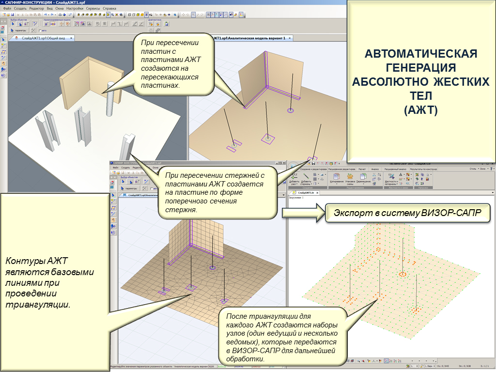
Perfectly rigid body (PRB) –generate PRB at places where elements intersect (columns and walls with floor slabs, walls
with walls, beams with walls, etc.) and then forward it to VISOR-SAPR module.
ASSEMBLAGE - automatic and/or computer-aided mode of defining the assemblage sequence for the structure as assemblage events.
Then it is possible to visualize assemblage process.
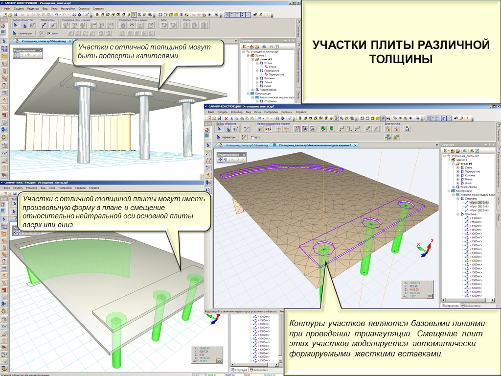
Slabs of different thickness – define slabs with arbitrary fragments of different thisckness, including capitals of different shape.
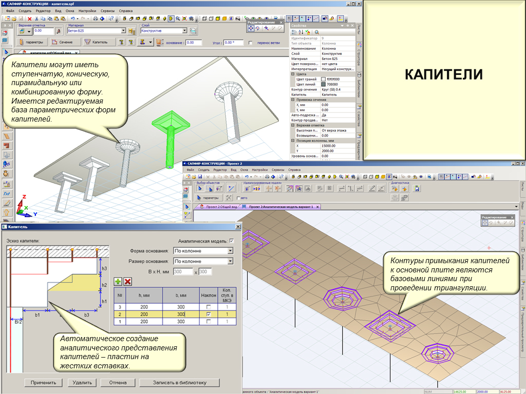
Capitals – create step-like, conic, pyramidal or combined shape and then forward it to VISOR-SAPR module.
Arbitrary inclined elements and ramps. To define ramps, specify projection of ramp to the lower floor slab and lines where ramp joins the lower and upper floor slabs. FE mesh of ramp corresponds to FE meshes of upper and lower floor slabs.
Loads - automatically generate models of service loads from type of premises, stipulated in architectural project, and loads from partititions and walls that are not load-bearing ones, with account of
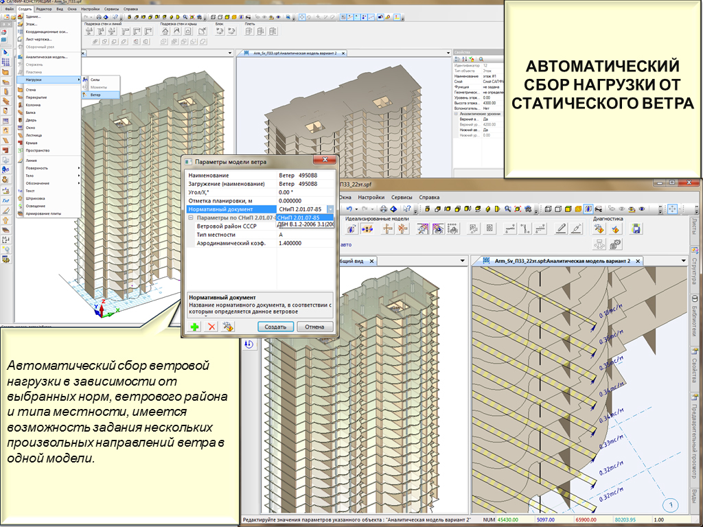
openings. Option to generate loads from static wind depending on selected building code, wind zone, type of region and direction of wind load.
Boundary conditions. On the analytical model the user defines the surface, line or separate node, as well as type of boundary conditions (numbers of DOF along which restraints should be imposed). After generation of FE mesh, all nodes (located in the specified surfaces, lines, etc.) will have boundary conditions of this type.
VISOR-SAPR module – generation of design model
Unified graphical user environment provides the following enhancements and modifications:
- Added option: to define bars with section variable along length. This bar may be defined as structural element that consists of several finite elements. Section parameters of separate finite elements included into such bar are calculated automatically. It is possible to visualize such bars as real sections on the 3D model.
- Updated dialog boxes, enhanced and unified design of interface elements in dialog boxes and on the toolbars.
- More options available for the ribbon user interface: on the ‘Analysis’ tab – option to analyse the model with account of NonLinear Engineering, on the ‘Design’ tab – option to evaluate analysis results for transverse punching shear reinforcement.
- New option to import models from Revit Structure 2013.
FEM-solver
New features of solver in LIRA-SAPR 2012 R3:
- New method for analysis of structures with account of physical nonlinearity. The main stages for analysis by this method
1.1. Define input data as for general analysis procedure.
1.2. Define ‘characteristic’ combination that (in the user’s opinion) will fully describe the stress strain states of elements of the structure.
‘Characteristic’ combination is defined as separate load case or a set of load cases that were defined for the whole analysis, every one with its own coefficient.
1.3. Nonlinear analysis is carried out by iteration method introduced by Birger. Stiffness parameters of sections are determined based on forces and reinforcement calculated at the last iteration stage. Stiffness variable along the length of bar (caused by physical nonlinearity) and, as usual, significant orthotropy for plates are considered.
1.4. According to obtained stiffness parameters, the program will automatically perform analysis for all load cases (including dynamic ones). In this case, DCF and DCL are calculated, analysis of reinforcement is carried out, and design procedure is provided in design modules of LIRA-FEM R3.
Advantages over the step-type method – input data definition is rather simple; time for analysis is by order of magnitude smaller; components of analysis results are similar to components of general linear analysis.
- Enhanced FE of shell and slab. Shear is considered; that enables you to analyse thick slabs (verification text "Test No.12").
- New element is introduced – bar of variable section. Section parameters are changed in linear way along the length of bar. All attributes (loads, boundary conditions) are similar to FE10.
- Modified earthquake analysis by accelerogram. Integration of accelerogram in time with account of dynamic factor is assumed as a basis for new method. New analysis enables you to bring results closer to analytical solution (verification test "Test No.3").
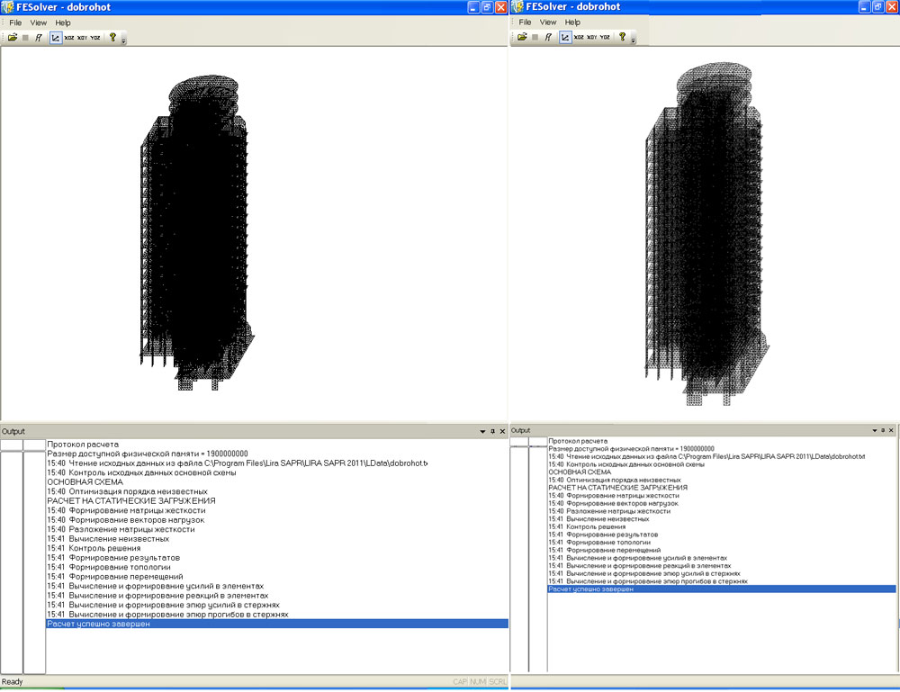
- Enhanced solver interface.
- Solver is available in two versions: 32-bit and 64-bit. Variant х64 makes it possible to use the whole RAM of computer (more than 2GB).
- The following options and features were clarified:
7.1. Masses are collected from elements – location of load on element is considered. In previous versions the total load was uniformly distributed between nodes of element.
7.2. Masses are collected from super-elements – location of loads applied inside super-element is considered. In previous versions the total load was uniformly dictributed between nodes of super-element.
7.3. Inertional forces are calculated – presence of local coordinate system of nodes is corrected.
7.4. ASSEMBLAGE system – modified analysis of model that includes super-elements.
7.5. Forces in elements for static component of wind pulsation. In previous versions, forces in bars with local load were calculated improperly for this component.
For convenience of users, option to use solver of previous version (LIRA-SAPR 2012 R2) is remained, partly because several modes (step-type analysis and stability) are not included into solver LIRA-SAPR 2012 R3 yet.
VISOR-SAPR Design mode
- New punching shear analysis of transverse reinforcement in reinforced concrete slabs.
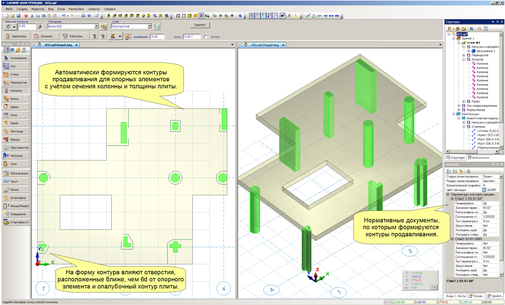
- In SAPFIR-Structures, punching shear contours are automatically generated
for selected columns depending on the following data: section of the column adjacent to the slab, slab thickness, openings or edge of the slab that are located nearby. The user could edit punching shear contours that are obtained automatically.
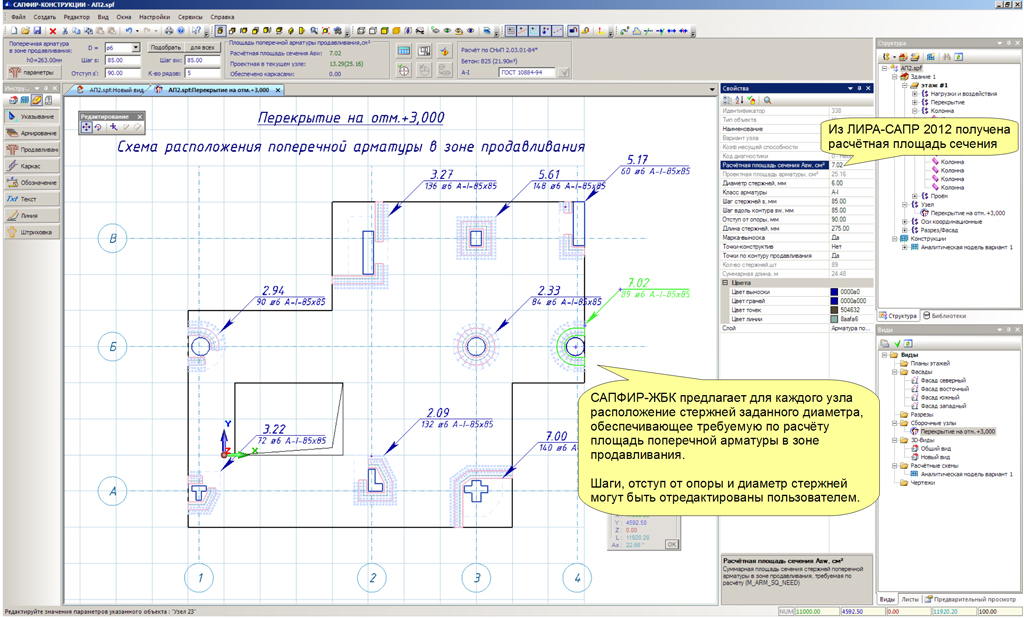
- o In VISOR-SAPR, forces (normal force and two moments) for punching shear analysis are calculated for selected columns for every load case. According to forces from load cases, for every column the program automatically generates DCF and determines punching shear reinforcement by different building codes (either with account of bending moments or not). Then it is possible to visualize punching shear reinforcement, punching shear contours and bearing capacity coefficients.
Analysis results are exported to Design of RC structuresstructures module for further design procedure.
- New alternative method for analysis of reinforcement for plates – Wood method. The user could define either Wood method or Karpenko method realized earlier. For some cases, Wood method provides you with more logical results but for heavily reinforced plates the reinforcement may be overstated.
- New graphical presentation of colour palette is introduced. It is also possible to define particular settings of colour palettes for analysis results of steel structures.
Module Design of RC structuresstructures includes new mode ‘Punching shear’.
‘Punching shear’ mode functions in this way:
In Design of RC structuresstructures, the following data is imported: punching shear contours, area of transverse reinforcement and drawing of formwork for the slab.
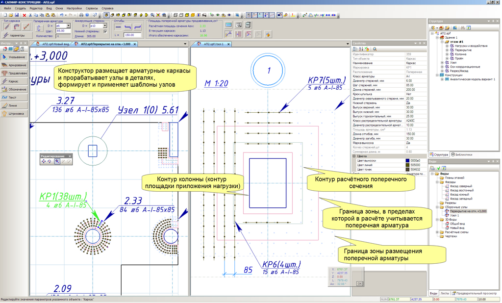
Rebars are arranged automatically in the punching shear zone according to area of punching shear reinforcement and defined diameter. The user could unify zones and for each unified zone automatically
unite them into reinforcement cages of different type (comb-type, rectangular or curvilinear cages, etc.).
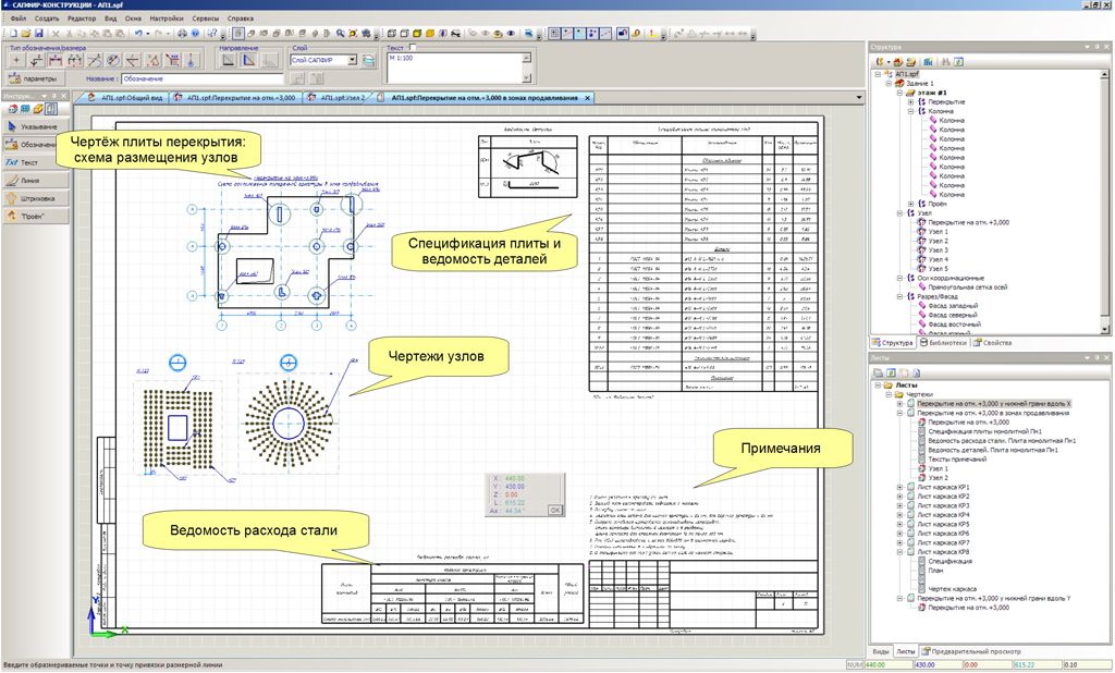
The drawing is generated automatically. The drawing contains pattern of reinforcement cages,
drawings of cages, specification of reinforcement, list of components and materials, notes.
|

Boundary conditions
|

Topological model (extension)
|

Perfectly rigid body (PRB)
|
ASSEMBLAGE
|

Slabs of different thickness
|
Capitals
|

Arbitrary inclined elements and ramps
|

Enhanced solver interface
|

Loads from static wind
|
Automatic generation of punching shear contour
|

Punching shear in VISOR-SAPR
|

Rebars are arranged automatically
|

Rebars are united into reinforcement cages, nodes are unified
|

Drawing is generated
|

Drawings of reinforcement cages
|
|


Comments