Eurocode 2. Reinforced concrete structures
LIRA-FEM* software supports a variety of national building codes, as well as European standards (Eurocodes) and national annexes to Eurocodes for Ukraine, the Republic of Kazakhstan, and the Republic of Belarus.
Eurocode 2. Reinforced Concrete Structures
LIRA-FEM (LIRA-SAPR) is mentioned to analyse the reinforced concrete structures, select and check the specified reinforcement in columns, beams, slabs, walls according to Eurocode requirements:
- EN 1992-1-1:2004, IDT 'Eurocode 2. Design of concrete structures. Part 1-1 -- General rules and rules for buildings';
- SP RK EN 1992-1-1:2004/2011 'Design of concrete structures' (Kazakhstan);
- Building codes of the Republic of Belarus TKP EN 1992-1-1:2009* (02250). Design of concrete structures. Part 1-1 -- General rules and rules for buildings.
To design reinforced concrete structures according to these standards, the LIRA-FEM has the necessary functions to define the input data and evaluate the obtained analysis results.
Element cross-sections
Rectangular, symmetric T-section, asymmetric T-section, symmetric I-section, asymmetric I-section, box, ring, round, angle, symmetric cross, asymmetric cross.
Classes for concrete and reinforcement
According to the specified building code.
Forces and stresses:
Forces in bars, stresses in wall-beams, linear forces in slabs, stresses and forces per r.m. in shells.
In the mode for analysis and design of reinforced concrete (RC) structures, it is possible to select the reinforcement for columns, beams (analysis of RC beam), slabs, walls and shells by the ultimate and serviceability limit states.
The arbitrary properties of concrete and reinforcement may be applied; it is very important in analyses related to the reconstruction. In this mode the user could combine several elements of the same type into a structural element and arrange the reinforcement along the whole length of such element.
1. Materials
1.1 Type of reinforcement: Bar
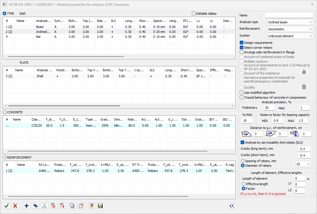
To select reinforcement according to Eurocode 2 (EN 1992-1-1:2004, IDT), Eurocode 2 (Belarus) (TPK EN 1992-1-1:2009*), Eurocode 2 (Kazakhstan) (SP RK EN 1992-1-1:2004/2011), general material properties are defined for the bar elements. The type of analysis is selected from the list: bar, beam, column, pylon or inclined beam.
To arrange the reinforcement in the section of the element, select the type of reinforcement: symmetric, asymmetric, symmetric and asymmetric. By default, the (corner) rebars are located at the corners of the RC section. For all analysis types except for 'bar', it is possible to take account of design requirements of the selected building code.
The distances to the centre of gravity of the reinforcement are defined for each individual analysis type (rows of parameters).
Analysis by serviceability limit states (SLS) may be carried out. For this analysis, define the following data: the ultimate crack propagation, diameter of reinforcement or the spacing for reinforcement (to compute diameter).
For eccentrically compressed elements, the element length and effective lengths should be defined.
Note. In contrast to the standard type of analysis 'Beam', the'Inclined beam' type allows the user to take into account the longitudinal compressive force as well as the lengths and effective lengths of the elements. The design requirements for beams may be taken into account.
1.2 Type of reinforcement: Plate
To analyse reinforcement according to Eurocode 2 (EN 1992-1-1:2004, IDT), Eurocode 2 (Belarus) (TPK EN 1992-1-1:2009*), Eurocode 2 (Kazakhstan) (SP RK EN 1992-1-1:2004/2011) in plate elements, the type of analysis is selected from the list in the general parameters (by default, the analysis type 'Shell' is selected). Reinforcement may only be selected according to Wood's theory.
It is possible to define different distances to the centre of gravity of the reinforcement in the direction of the local X-axis and local Y-axis at both the top and bottom faces. If the same distances are defined to the top and bottom faces, then the reinforcement will be selected in the middle of the plate element cross-section.
Analysis by serviceability limit states (SLS) may be carried out. For this analysis, define the following data: the ultimate crack propagation, diameter of reinforcement or the spacing for reinforcement (to compute diameter).
For vertical plate elements of wall, it is possible to define information about the height and effective height of the wall. For the arrangement of reinforcement in the wall section, the type of reinforcement is selected: symmetric or asymmetric.
1.3 Properties of concrete
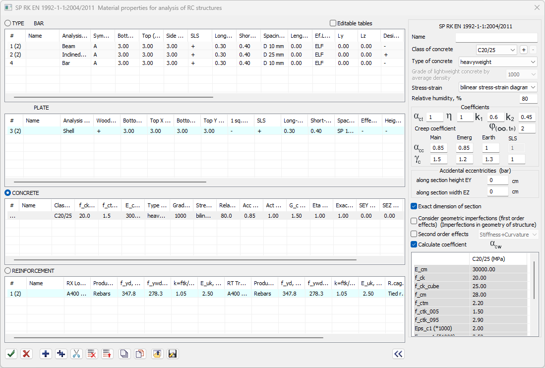
In the concrete properties, define the concrete type, concrete class and concrete state diagram. It is possible to set coefficients for concrete strength. By default, the recommended values for the selected normative document are set.
Accidental eccentricities are defined in order to increase the moments, taking into account the second order effects in eccentrically compressed bar elements. The minimum accidental eccentricities are calculated automatically.
Stress-strain diagram
The parabolic-rectangular diagram or the bilinear diagram is chosen as the design diagram for the state of compressed concrete by paragraphs 3.1.7 (1) and 3.1.7 (2) of SP RK EN 1992-1-1:2004/2011. These diagrams show how stresses and relative strains relate to one another.
Relative air humidity
The relative humidity (%) is defined to determine the nominal free shrinkage on drying of concrete with CEM cement of class N by clause 3.1.4 (6) of SP RK EN 1992-1-1:2004/2011.
αct - coefficient taking account of long term effects (tension)
According to clause 3.1.6 (2) of SP RK EN 1992-1-1:2004/2011, a coefficient αct is defined to take into account the long term effects on the tensile strength and the unfavourable effects resulting from the way the load is applied.
Conversion factor η to reduce γc based on testing in a finished structure or element
For concrete strength values that are based on testing in a finished structure or element, the partial safety factor γc may be reduced by conversion factor η. See clause A.2.3 (1) of SP RK EN 1992-1-1:2004/2011.
Coefficients which limit the stress
According to clauses 7.2 (2) and 7.2 (3) of SP RK EN 1992-1-1:2004/2011, the coefficients for analysis by serviceability limit states are as follows: k1, which limits compressive stresses in concrete, and k2, which limits compressive stresses in concrete during creep (which controls the choice of creep model). The recommended values are 0.3...1.
Creep coefficient
The final value of creep coefficient φ(∞, tn) is defined according to clause 3.1.4 (5) of SP RK EN 1992-1-1:2004/2011.
αcc - coefficient taking account of long term effects (compression)
According to clause 3.1.6 (1) of SP RK EN 1992-1-1:2004/2011, a coefficient αcc is defined to take into account the long term effects on the compressive strength and of unfavourable effects resulting from the way the load is applied. By default, αcc is taken as equal to 0.85, for emergency combinations - as 1.2, for earthquake combinations - as 1. In analysis by serviceability limit states, it is always taken as equal to 1. The recommended values are 0.8...1.
γc - safety factor
The partial factor (safety factor) for concrete γc for persistent and transient (long-term and short-term) design situations is defined according to clause 2.4.2.4 (1) of SP RK EN 1992-1-1:2004/2011. By default, γc is taken as equal to 1.5, for emergency and earthquake combinations - as 1.2, for analysis by serviceability limit states (check for cracks) - as 1. The recommended values are 1...2.
Accidental eccentricities (bar)
Accidental eccentricities in two directions of the section in the X1OZ1 (EY, moment My) and X1OY1 (EZ, moment Mz) planes are defined.
Exact geometrical parameters in design
Option to modify the partial safety factor for materials in case there are accurately measured dimensions; see clause A.2.2 SP RK EN 1992-1-1:2004/2011.
First order effects (Geometric imperfections)
Option to take into account the first order effects (unfavourable effects without taking into account the strain of the structure, but with account of geometric imperfections), see clause 5.2 of the SP RK EN 1992-1-1:2004/2011.
Second order effects
Option to take into account the second order effects (additional unfavourable effects due to strain of the structure), see clause 5.1.4 of the SP RK EN 1992-1-1:2004/2011. In the list, select for which calculations they should be taken into account (Stiffness+Curvature, Stiffness, Curvature).
Table of design parameters
For the selected concrete class, the normative and design parameters are displayed:
- E_cm - modulus of elasticity;
- f_ck - characteristic compressive cylinder strength of concrete at 28 days;
- f_ck_cube - characteristic cube compressive strength of concrete at the age of 28 days;
- f_cm - mean value of concrete cylinder compressive strength;
- f_ctm - mean value of axial tensile strength of concrete;
- f_ctk_005 - characteristic axial tensile strength of concrete;
- (other).
The table may be modified for additional, user-defined classes of concrete.
1.4 Properties of reinforcement
Class, type and strength of longitudinal reinforcement
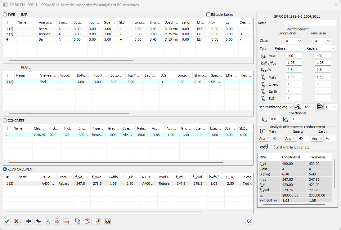
In the list, select the class of longitudinal reinforcement: A, B, C. The type of longitudinal reinforcement is selected from the list according to t. C.2N of SP RK EN 1992-1-1:2004/2011. The characteristic (normative) yield strength of the longitudinal reinforcement is specified - yield strength fyk according to t. C.1 SP RK EN 1992-1-1:2004/2011.
Class, type and strength of transverse reinforcement
The class and type of transverse reinforcement are selected from the lists. The characteristic (normative) yield strength of longitudinal reinforcement fyk is defined.
Ductility characteristics. Tensile strength to yield strength ratio
For longitudinal and transverse reinforcement, define the ratio k=ftk/fyk of the tensile strength of the reinforcement to the yield strength, the minimum value, according to t. C.1 SP RK EN 1992-1-1:2004/2011.
Ductility characteristics. Characteristic strain at maximum force
For longitudinal and transverse reinforcement, the characteristic strain (maximum elongation) at maximum force μuk, % is specified according to t. C.1 SP RK EN 1992-1-1:2004/2011.
Partial factor
For longitudinal and transverse reinforcement in analysis by ultimate limit state (ULS) for persistent and transient design situations, the partial factor is is defined according to clause 2.4.2.4 of SP RK EN 1992-1-1:2004/2011. By default, both coefficients is are taken as equal to 1.15, for emergency and earthquake combinations - equal to 1, for serviceability limit states (SLS, check for cracks) - equal to 1. The recommended values are 1...2.
Type of reinforcing cage
The type of reinforcing cage (tied, welded) is selected from the list.
Maximum diameter
For bars, the maximum diameter of longitudinal reinforcement used in strength analysis of reinforcement is defined (6, 8, 10, 12, 14, 16, 18, 18, 20, 22, 25, 28, 32, 36, 40).
Number of rebars in section corners
To select reinforcement with the corner rebar selection algorithm, the number of rebars located in the corners of the section should be defined.
Steel tables
Define the range of diameters that should be applied.
Coefficients which limit the stress
According to clauses 7.2 (5) of SP RK EN 1992-1-1:2004/2011, the coefficients for analysis by serviceability limit states are as follows: k3, which limits tensile forces in reinforcement, and k4, which limits tensile forces in reinforcement in forced strain. The recommended values are 0.3...1.
Analysis of transverse reinforcement
To calculate transverse reinforcement by truss model, the angles θ between the concrete compressed diagonal element and the beam axis perpendicular to the transverse force are specified separately for basic (persistent and transient design situations), emergency and earthquake combinations. In the appropriate list, define the method to determine the following data: Analysis (the angle will be computed), Angle (it is necessary to define the angle from 21.8 to 45В°), Range (angles in the range of 21.8...45В° will be used for analysis). For the ultimate values of the angle θ, see clause 6.2.3 (2) of SP RK EN 1992-1-1:2004/2011. When the certain check box is selected, the value of ctg θ may be 'limited with the length of the StE' (length of the structural element).
Table of design parameters
For reinforcement classes (longitudinal, transverse), the normative and design parameters are displayed:
- fyk - characteristic (normative) yield strength of longitudinal reinforcement;
- class;
- D - diameter, mm;
- fyd - design yield strength of longitudinal reinforcement;
- ftk - characteristic (normative) tensile strength of reinforcement;
- fywd - design yield strength of stirrups;
- Es - modulus of elasticity;
- k (ftk/fyk) - ratio of tensile strength of reinforcement to yield strength, minimum value;
- eps_uk - characteristic strain at maximum force.
2. Analysis of reinforcement in bar elements
To analyse reinforcement in bars, the universal iterative optimizing methods are implemented; so using the same method it is possible to analyse sections:
1 - of arbitrary shape (rectangular, cross, T-section, I-section, box, angle, circular, ring);
2 - with arbitrary arrangement of reinforcement;
3 - on arbitrary types of stress strain state, such as flat bending, oblique bending, bending with torsion, flat eccentric compression - tension, simultaneous action of all six types of forces - N, Mx, My, Mz, Qy, Qz.
The fundamental provisions of the building codes are implemented in analysis of reinforcement.
Optimising principles are implemented in the iterative algorithms: reinforcement in the most stressed areas of the section is increased as a priority, and the mutual influence of reinforcement selected according to different DCLs is considered. The realised algorithms meet the requirements of slenderness, as the user could assign the modes of rebar selection:
- select the type for arrangement of reinforcement in the cross-section (symmetric relative to one or two principal axes of the cross-section, uniform arrangement of reinforcement along certain faces, arbitrary arrangement of reinforcement);
- assign the 'corner bars' mode, in which the reinforcement area is increased mainly in the corner zones according to the universal algorithm; in some cases, this strategy can help you use 20-30% less reinforcement than in alternative cross-sectional reinforcement arrangements;
- assign max diameters of rebars when the reinforcement is analysed by serviceability limit state, as the smaller diameters improves the strength of the RC element to cracks and in this case the area of the required reinforcement may be significantly reduced;
- adjust parameters of the iterative process, slightly reducing the accuracy in analysis of reinforcement (in this case the error may be 3-5%), but significantly increasing the speed of the algorithm and vice versa.
3. Analysis of reinforcement in plates
In LIRA-FEM it is possible to analyse reinforcement area for plate elements according to Wood's theory. There is an algorithm to obtain the area of reinforcement for plate elements by Wood's theory with optimisation of tangential stresses.
When the 'Ductility' option is selected, then in the analysis of RC sections according to SP RK EN 1992-1-1:2004/2011, TKP EN 1992-1-1-2009*, EN 1992-1-1:2004, IDT it is possible to use a modified algorithm to check equilibrium and calculate stresses and strains at arbitrary points of the section. For the Wood-Armer method, this algorithm is used to analyse reinforcement by ultimate and serviceability limit states. This method enables the user to make the analysis faster and to obtain a smoother distribution of reinforcement in the plane of the plate. This algorithm is implemented in the analysis according to SP RK EN 1992-1-1:2004/2011, EN 1992-1-1:2004, DBN B.2.6-98:2009, TKP EN 1992-1-1:2009, DSTU-N B EN 1992-1-1:2010.
4. Pilot reinforcement (PR types)
To check the load-bearing capacity of sections of bar and plate elements according to the current building codes in the LIRA-FEM software, the engineer can use the specified real reinforcement pattern.
It is possible to specify the reinforcement pattern of any complexity in plates and bars as quickly as possible using the types of pilot reinforcement.
After the check of the bearing capacity of sections with a specified reinforcement according to SP RK EN 1992-1-1:2004/2011, TKP EN 1992-1-1-2009 *, EN 1992-1-1:2004, IDT, the reserve factor for load-bearing capacity will be obtained for each plate and in each section of bar.
Strength analysis of the specified longitudinal reinforcement: for bars - in N, My, Mz, for plates - in Mx, My, Mxy, Nx, Ny, Txy. The following checks are also available:
- complete check (including the check for the combined action of torque and shear force and the combined action of torque and bending moment),
- for strength,
- for torque (bars),
- for shear forces,
- for crack propagation.
5. Punching shear analysis
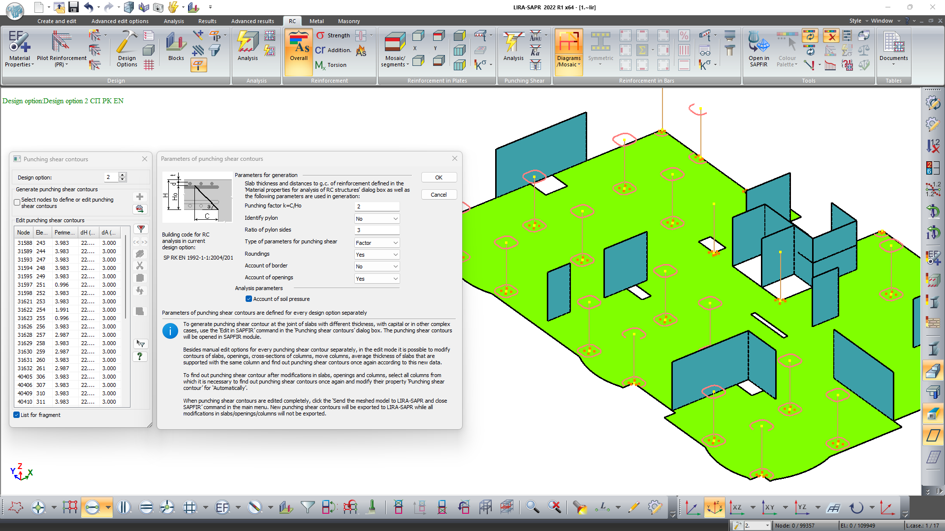
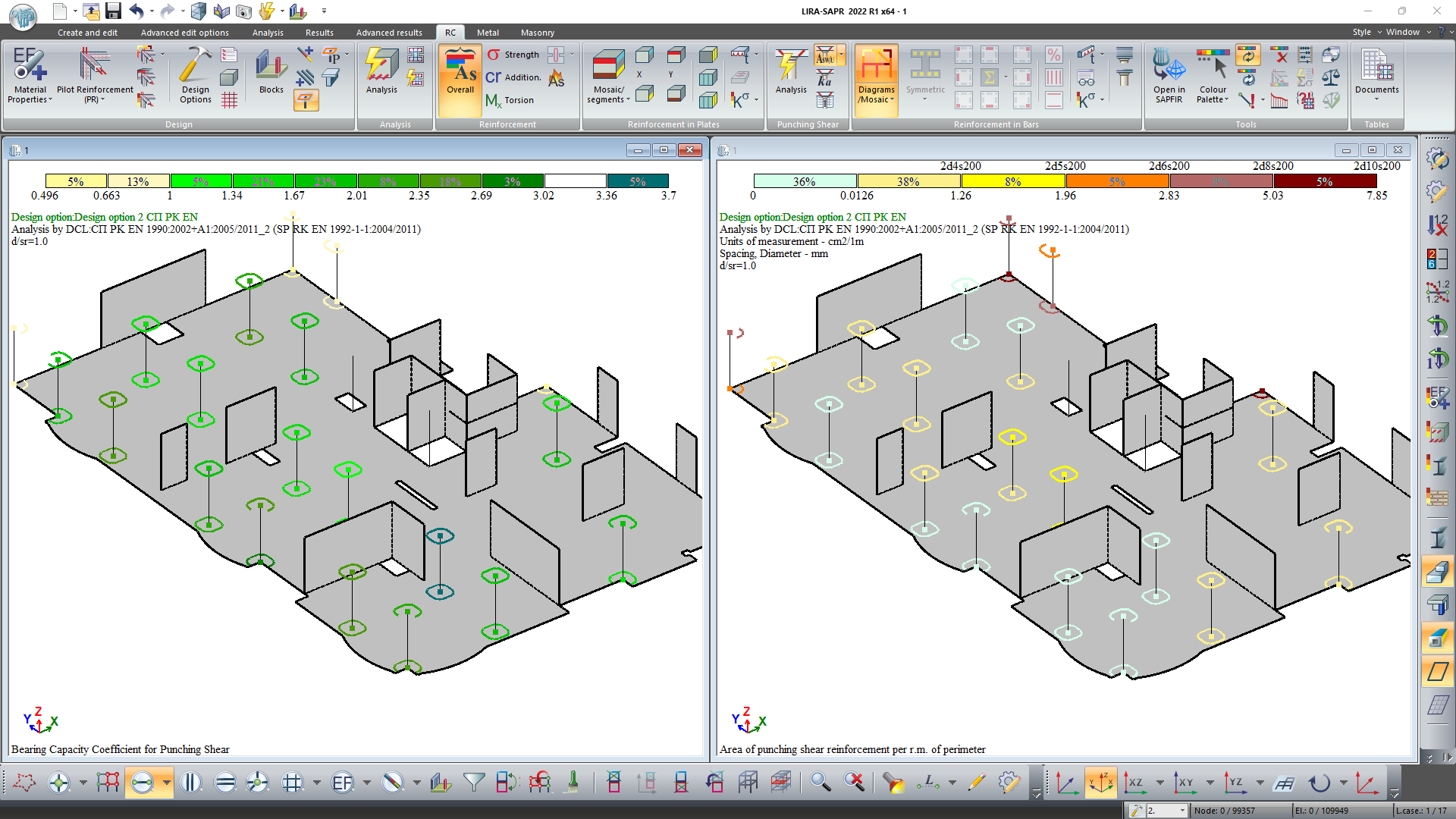
The FEM model is prepared for punching shear analysis of beamless slabs and foundation slabs. Such technology implemented in the LIRA-FEM enables the user to add necessary data for the punching shear analysis of the model according to a certain building code, track all changes in the model, edit contours, and evaluate the obtained results.
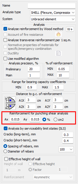
To determine the reinforcement ratio (used for analysis of punching shear slab), either the area or percentage of reinforcement of the slab along the directions of the unified X and Y axes is additionally specified in the materials. If this data is not specified, the reinforcement ratio will be taken as equal to 0.02.
6. Analysis of reinforcement (Local mode)
LARM module (local mode of reinforcement) is mentioned to analyse the reinforcement for an individual RC bar or plate element according to SP RK EN 1992-1-1:2004/2011, EN 1992-1-1:2004, TKP EN 1992-1-1:2009.
In this module it is possible to make multiple changes of section parameters, geometric properties of the element, pilot reinforcement for the section, material properties, forces or design combinations of loads (DCL) and analyse the reinforcement.
- The design is carried out automatically with interactive graphical methods based on the analysis results of the reinforcement presented as contour/mosaic plots of the reinforcement area.
- The following data is indicated on the drawings:
- main reinforcement,
- pattern of additional reinforcement with account of anchorage and overlapping,
- parameters of reinforcement,
- notes.
RC Design module imports the analysis results of reinforcement from VISOR module and shows contour plots and mosaic plots of reinforcement as a background for the slab. The scale for presentation of analysis results and the selection of the main reinforcement are adjusted, and the contour plots are automatically changed. The engineer defines patterns for additional reinforcement on the background of contour plots.
In this module you could see places with insufficient reinforcement in the slab as mosaic plot. When the additional reinforcement is modified graphically, the mosaic plot with insufficient reinforcement is also modified.
It is possible to unify different items in the specification of reinforcement.
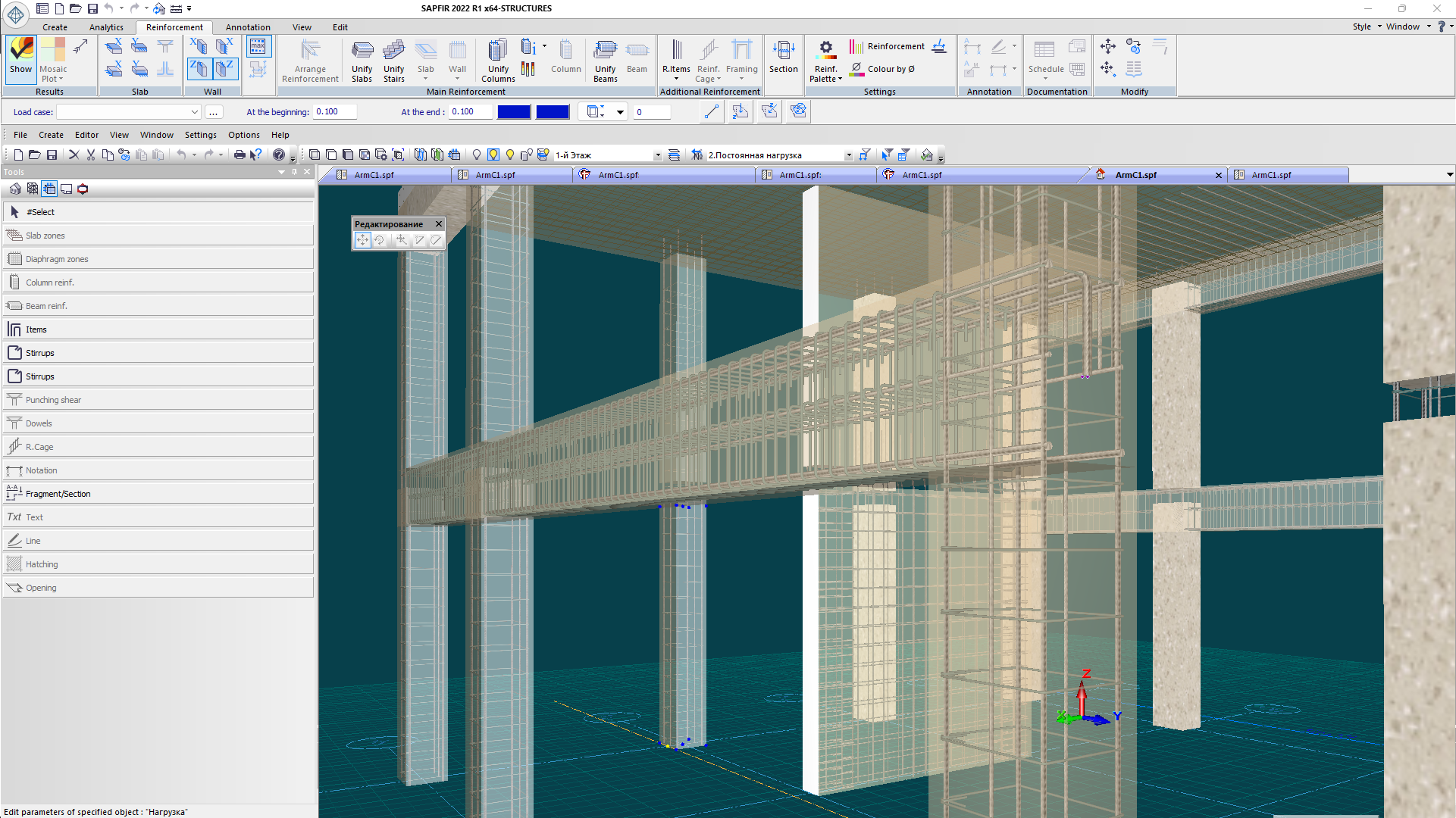
Drawing sheets - layout of reinforcement patterns - are generated automatically. The sheet can optionally contain: reinforcement specification, list of components, steel consumption list.
Evaluate the software
If you have any doubt, download the Demo version and evaluate the program or contact our Support Team for more details.


