LIRA-SAPR 2014
New program version is introduced – LIRA-FEM version 2014. Structural blocks; Visualization of nonlinear analysis; Loads on fragment; New options in Ribbon User Interface; Eurocode 2 EN 1992-1-1:2004 and more
VISOR-SAPR
Structural blocks are taken to mean arbitrary fragments of the structure, such as columns, beams, walls, slabs, frames, storeys, etc. assigned as structural blocks. With these blocks and their names / labels, it is much easier now to find, select and fragment separate elements of buildings and structures on design model.
The whole structure may be divided into structural blocks or separate finite elements may be grouped to appropriate structural blocks. Both these procedures are carried out automatically. In this case, the program applies integrated algorithms that examine location of separate objects and their geometry. It is also possible to define structural blocks manually.
Different parameters such as ‘type of structural block’ (StB type), ‘storey’, ‘label’, ‘comments’, ‘colour’ for presentation on model, ‘stiffness’, ‘materials’, etc. will simplify the work with structural blocks. These parameters may be modified.

Structural blocks
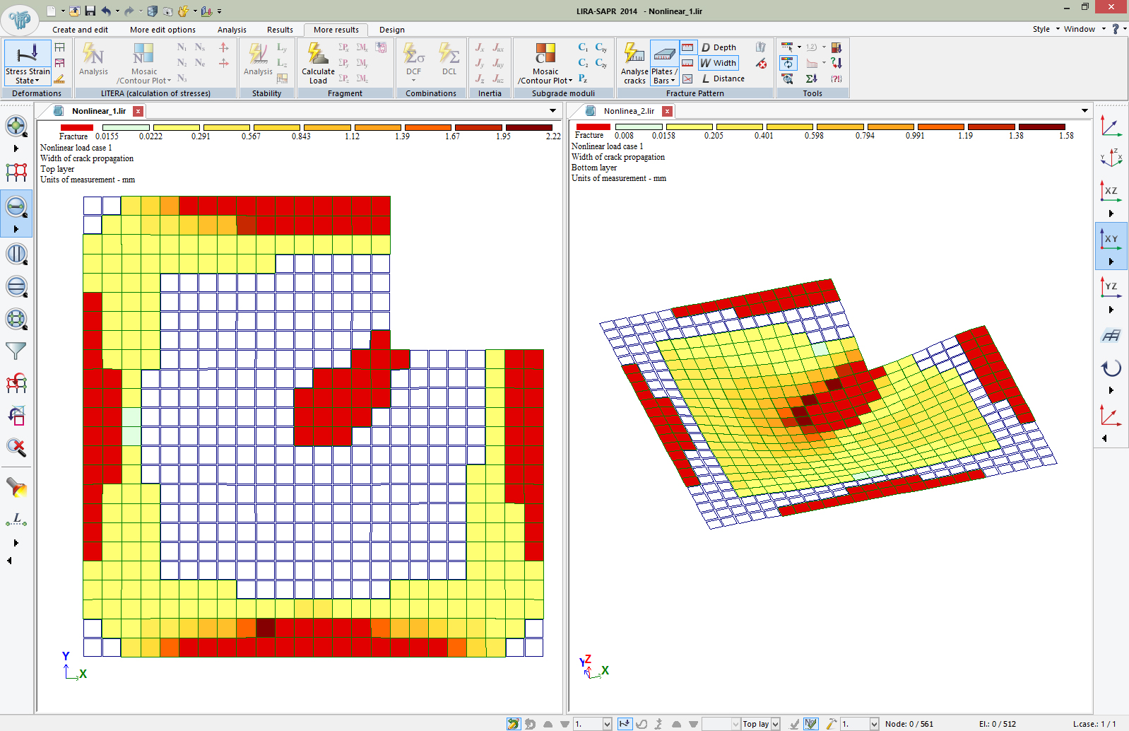
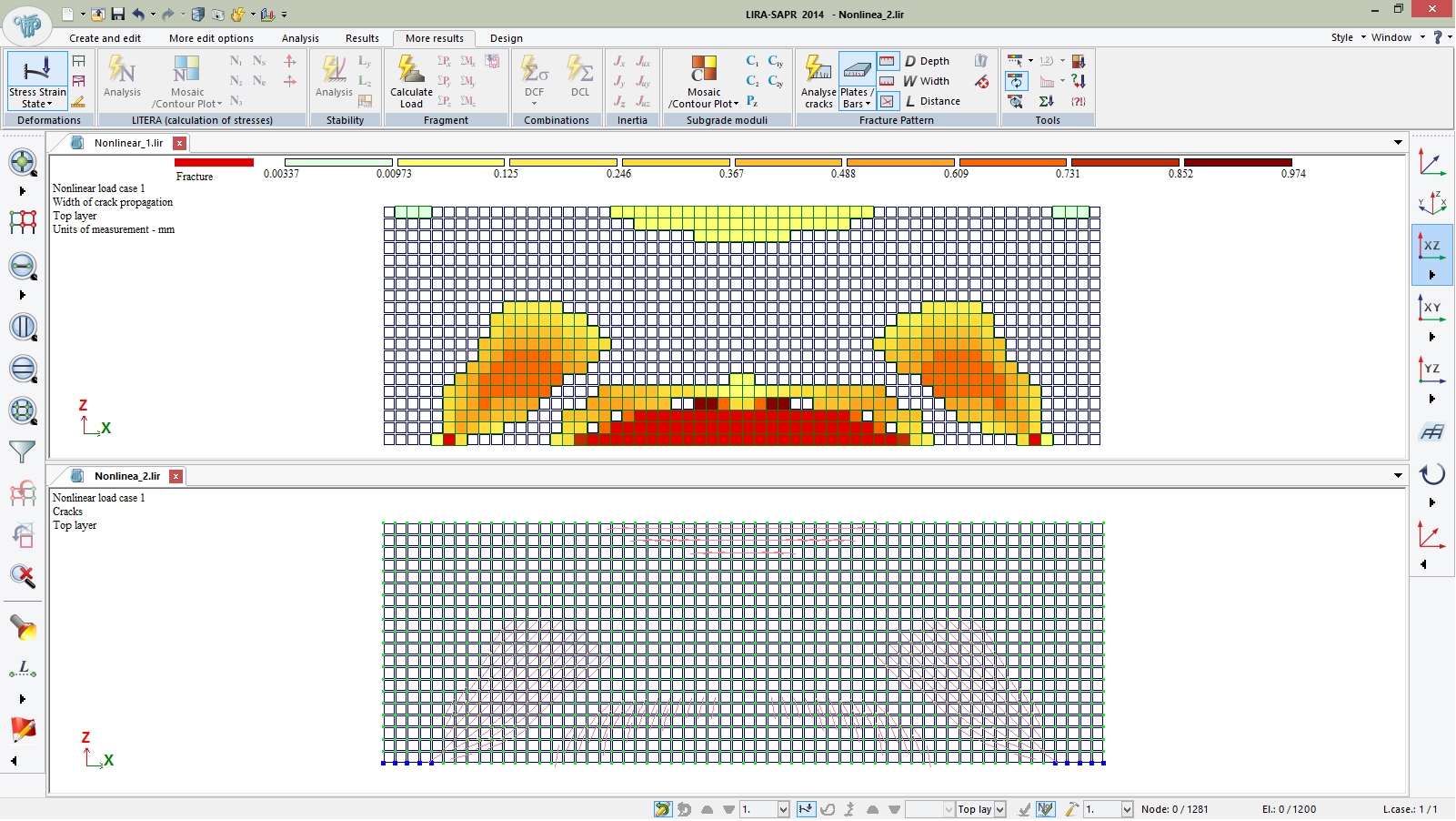
Updated algorithm based on step-type methods is realized for analysis of problems with physically nonlinear materials and problems with account of creep. Options for output data are enhanced. In addition to traditional data about nonlinear displacements and forces, it is possible to output data about width and depth of crack propagation in bar and plate elements. This data is presented as mosaic and colour plots. You could also review and prepare documents with output data not only for the last but for any intermediate step of the specified nonlinear history of load cases.
 |  |
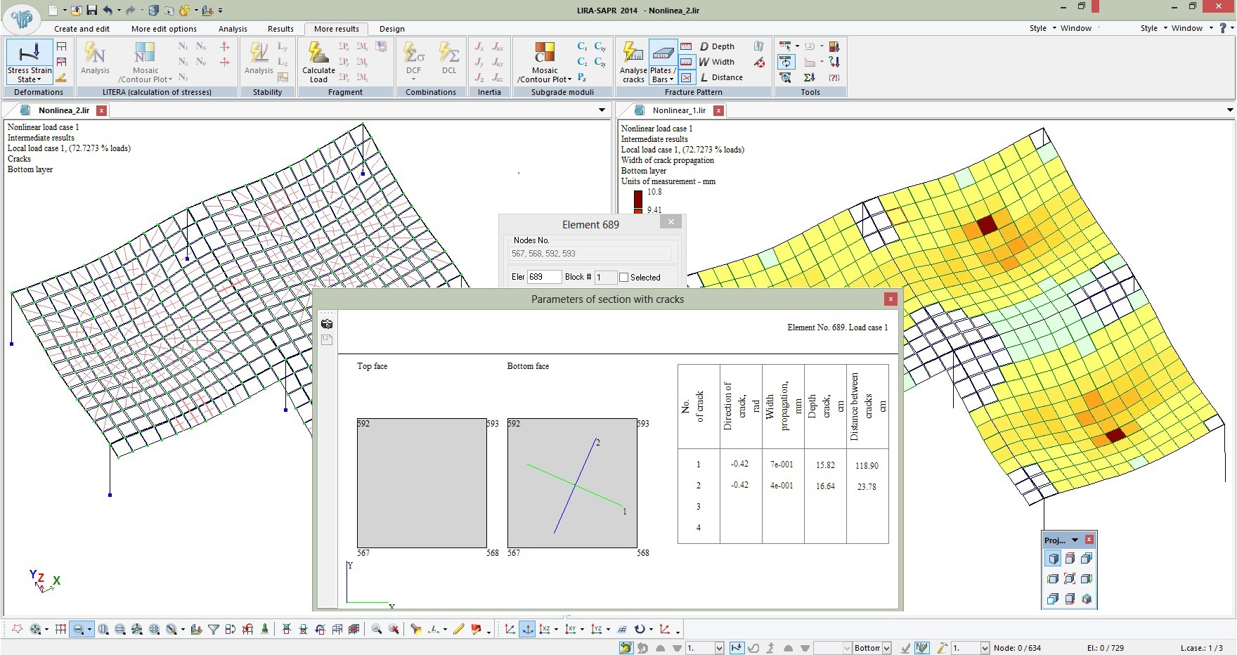 |  |
| Visualization of nonlinear analysis | |
When generating force diagrams for bar systems, local load is considered.
Enhanced options for analysis of loads on fragment. For super-element problems it is possible to obtain loads on fragment not only at super-nodes of the main model but at specified internal nodes of super-elements as well.
New styles for Ribbon User Interface are presented: ‘Ribbon RC’, ‘Ribbon Steel’, ‘Ribbon Plus’.
With ‘Ribbon RC’ and ‘Ribbon Steel’ styles, the user could obtain quick access to special tools for the detailed evaluation of analysis results in appropriate program modes.
The Help system contains a guide for composing Ribbon Interface in User-defined style.
New toolbar ‘Projection 2’ that simplifies the work with design model.
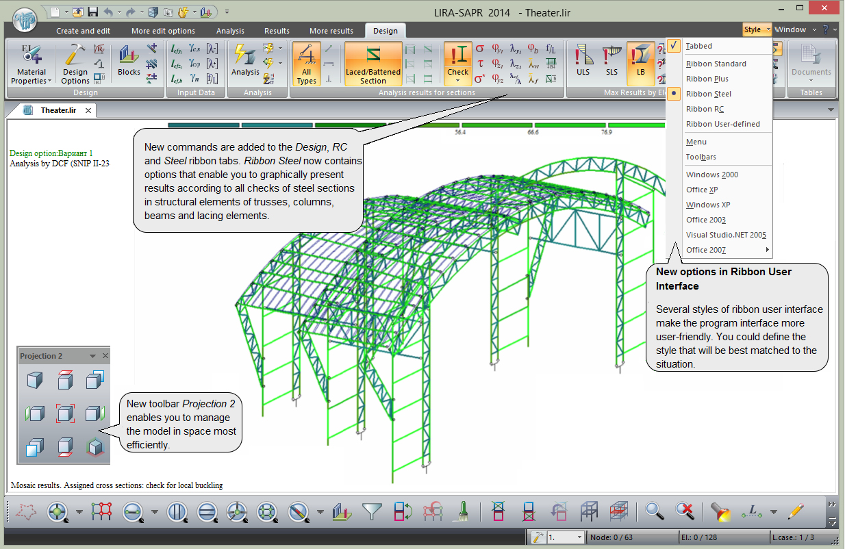
New options in Ribbon User Interface
FEM-solver
New procedures to determine parameters of stress strain state in sections of nonlinear bar and plate elements. These procedures have made it possible to avoid numerous alogisms and imperfections that appeared in some cases in previous versions of LIRA program, including LIRA version 9.6. Such imperfections contained: fracture of structure at first steps of load application, increase of forces in elements that are already destroyed; considerable difference in output data obtained from dependencies σ-ε defined analytically (for example, by exponent) with piecewise linear functions.
Output data may be displayed for every step of load application. When generating force diagrams for nonlinear bars, local load is considered.
Creep theory presented in Eurocode is realized completely – creep value depends not only on time but on stress as well.
Load compensation method is realised for problems of structural nonlinearity (e.g. one-way springs).
In previous versions of the program (including LIRA version 9.6), the FEM-solver computed required number of iterations beforehand. If the specified precision is not reached after these iterations are complete, the analysis was terminated. New FEM-solver performs as many iterations as necessary to obtain solution with required precision, that is, the user will always obtain solution. In case the system with elements of structural nonlinearity is geometrically unstable, appropriate warning is displayed on the screen.
Analysis of reinforced concrete structures (ARM-SAPR)
Eurocode 2 EN 1992-1-1:2004 with account of regional application for Republic of Kazakhstan CH PK EN 1992-1-1:2004/2011 is supported.
 METEOR (Method of unified integrated result)
New system that enables the user to merge problems with the same topology – nodal coordinates, FE model, geometry of sections. Problems may differ in load cases, stiffness and boundary conditions.

METEOR system (merging problems with the same topology)
The merged problem will contain topology, stiffness, design options of the basic problem and analysis results of all problems. For such merged problem the user will define and calculate unified DCF. Design procedure is carried out according to these DCF by specified design options.
For example, you generate FE model that is common for all problems.
1st problem – analysis on dead and live loads.
2nd problem – analysis on earthquake and widn loads with modified parameters of soil (subgrade moduli C1 and C2).
3rd problem – analysis on predefined displacements (undermining, settlements).
Then you merge these problems and generate one (merged) problem to obtain unified DCF for these three problems.
Previous system MODEL VARIATION is a special case of new METEOR system.
Analysis of steel structures (STC-SAPR)
Truss joints of pipe elements
Analysis of parametric truss joints of pipe (circle section) elements – 9 basic joints and 6 variations. Layout for adjoining elements is available, weld length is calculated. Analysis is carried out according to SP 16.13330.2011.
Output data is presented as report file with utilization ratio for bearing capacity of every element included into joint. This gives an accurate account of element behaviour and enables the user to design the joint in the optimal way. Tracing routine for analysis precedure may be presented.
 |  |
| Truss joints of pipe elements | |
Corrosion (Release R2 – June 2014)
New option – ‘Corrosion’. For sections of steel elements it is possible to define depth of corrosion in mm. In this case, new geometric properties are computed with account of thinning from corrosion. There properties will be applied for static analysis and for check procedure in the mode of analysis of steel structures (STC-SAPR).
Beam with corrugated or flexible web
New option: export STC-SAPR → Platon-Structure in order to select and check beams (with corrugated or flexible web) for strength and buckling.
Design of RC structures
In addition to SLAB and DIAPHRAGM systems presented in Design of RC structures earlier, new system COLUMN is introduced.
The user could unify columns according to reinforcement data imported from LIRA-SAPR. The column is reinforced automatically.

Reinforcement in column
The user could also obtain working drawings for column reinforcement, specifications of reinforcement, lists of components and identification (marking) plan of columns and walls with specification of RC elements. Dimensions for column cross-sections may be displayed automatically.

Reinforcement in column
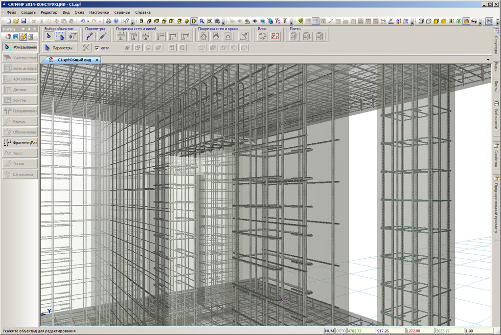
3D reinforcement
SAPFIR-Structures
Boundary conditions (Release R2 – June 2014).
At places where floor slabs are supported with walls, it is possible to define boundary conditions (hinge, hinge with eccentricity, free). You could also define boundary condition as for one arbitrary element is supported by another arbitrary element. According to this data, appropriate modifications (‘throwing apart’ nodes, inserting PRB, coupled DOF, etc.) will be automatically done in FE model.
Structural blocks (StB) that contain data about StB type (wall, column, beam, slab), storey where the StB is located, StB label, stiffness properties, as well as colour and comments may be exported to VISOR-SAPR module.
For loads imported to VISOR-SAPR, types of load cases (dead, live, short-term) as well as load factors and duration coefficients are assigned automatically and may be modified later.
Walls, beams, columns, ‘prism’ and ‘other’ objetcs may be modified manually. You could modify analytical model while its physical model remains the same.
For beams, the program has an option to automatically extend / shrink physical and analytical models by walls, columns, beams and floor slabs.
Imported IFC models may be modified in semi-automatic mode. New options that enable the user to transform certain types of objects (walls, columns, beams, slabs, prisms, etc.) into another ones, for example, walls into columns, columns into beams, beams into slabs, etc.
New options for import of IFC model generated in ArchiCAD: interpretation of object (bearing element, load) is considered in import procedure, improved identification of floor slab openings generated with nonstandard tools.
Shape creation mode that enables the user to generate framework of the structure by existing 3D-shapes (prism, surface of revolution, cone, sphere, etc.). 3D-shapes are automatically divided into storeys with optional generation of slabs and columns.
Comments