

Structural Analysis and Design to Eurocodes
The multifunctional research and sports center in Kaunas is an example of the integrated use of LIRA-FEM and LIRA-CAD for structural analysis and building design in accordance with Eurocode requirements. The project included modelling of load-bearing structures, load definition, linear and nonlinear analyses for ULS and SLS, as well as analysis of RC and steel structures.
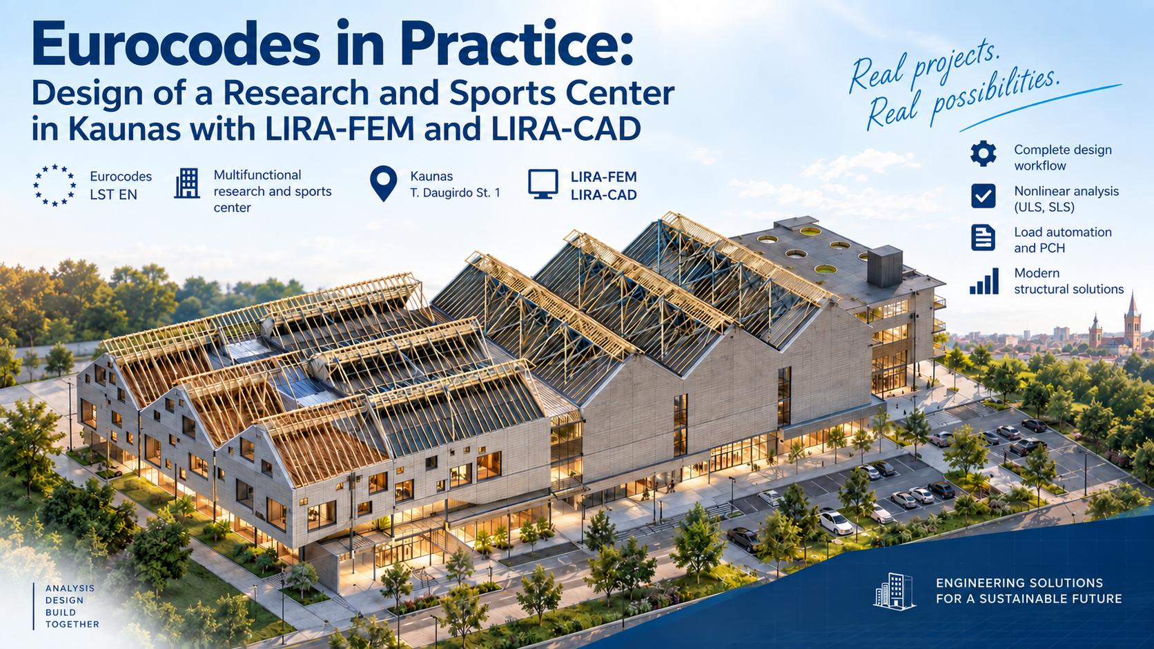
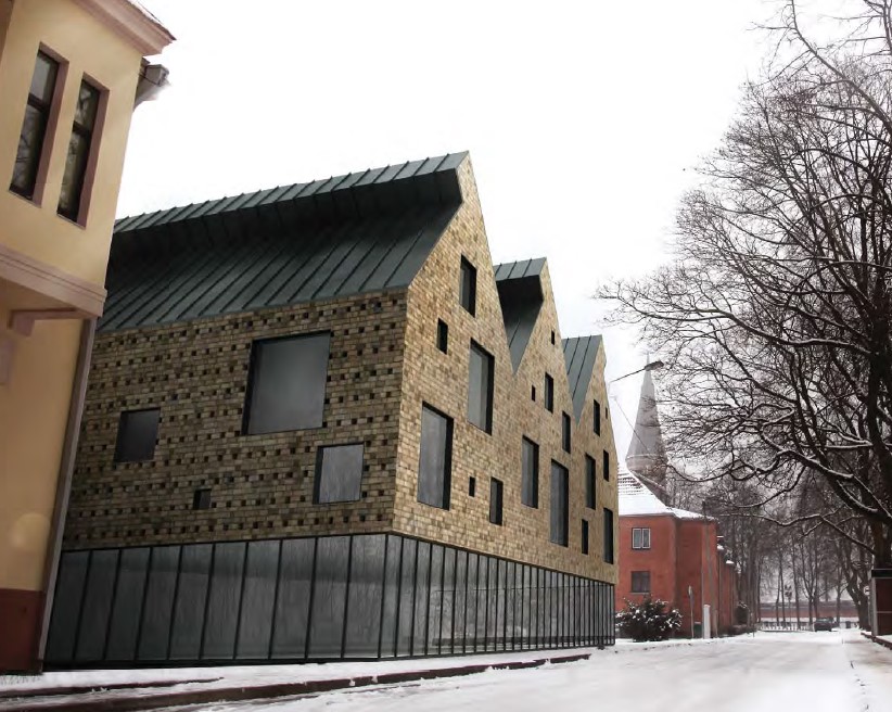
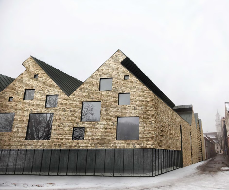
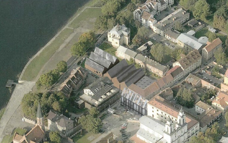
Multifunctional research and sports center at 1 T. Daugirdo St., Kaunas, using LIRA-FEM and LIRA-CAD in accordance with the Eurocodes
|
|
The purpose of this article is to demonstrate the capabilities of LIRA-FEM and LIRA-CAD for a complete cycle of structural analysis in accordance with the Eurocodes.
Project description:
Characteristics
-Consequence class by LST EN 1990:2004 – CC3.
-Reliability class by STR 2.05.03:2003 – RC2.
-Design working life by LST EN 1990:2004 – 50 years.
-Building type by use by STR 1.01.03:2017 – Non-residential building, subgroup (7.11) - buildings for research and educational purposes.
-Category by STR 1.01.03:2017 – special buildings.
-Type of construction by STR 1.01.08:2002 – new construction.
Main design solutions
The research and sports center has plan dimensions of 85 × 32.8 m. The building height is 13.75 m from the design elevation ±0.00. The floor level of the lowest storey is at elevation –3.9 m (relative to ±0.00).
The main load-bearing structures are cast-in-place reinforced concrete. The roof load-bearing structures are steel with timber rafters. The building is divided into two temperature zones and is constructed in three stages.
Interaction with adjacent buildings:
The building has no rigid structural connection to the existing buildings and is separated from them by retaining walls and an expansion joint.
Structural system
Cast-in-place reinforced concrete foundations on bored piles. The perimeter of the underground part is formed by pile walls. Cast-in-place reinforced concrete plinth beams; walls of staircases and elevator shafts; columns; floor slabs (beam-and-slab systems are used in zones with high loads). Pitched roofs are supported by steel trusses and timber rafters. Slabs are rigidly connected to columns and walls. Columns are cast-in-place reinforced concrete. Staircase walls and elevator shafts are flexibly connected to the foundations. Steel beams and trusses are hinged to reinforced concrete structures.
Stages of model generation
LIRA-CAD
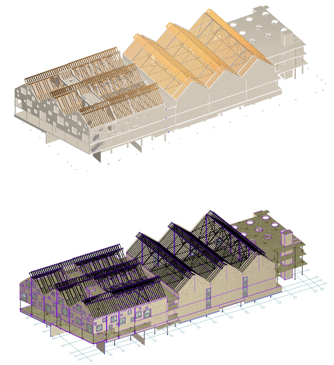
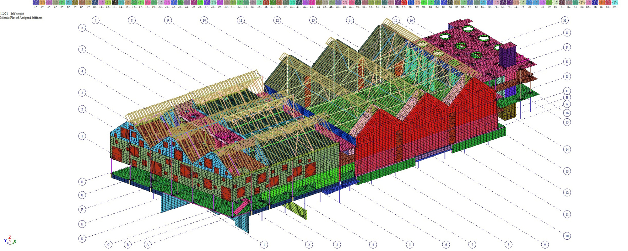
The model was fully developed in LIRA-CAD. All main load-bearing elements were modelled, with cross-sections, structural elements, material properties, boundary conditions and loads defined. Area loads were automatically converted into line loads applied to each rafter.
LIRA-FEM
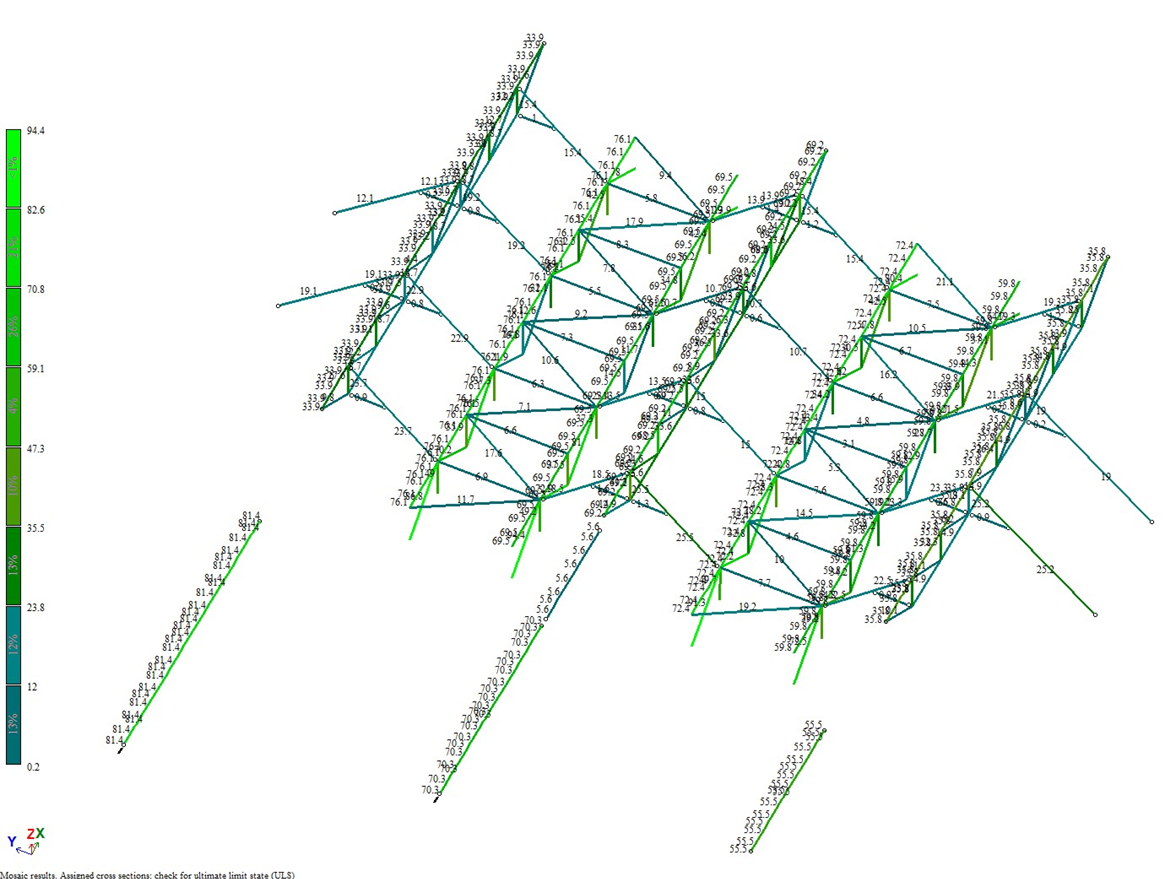
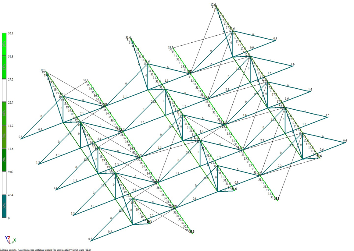
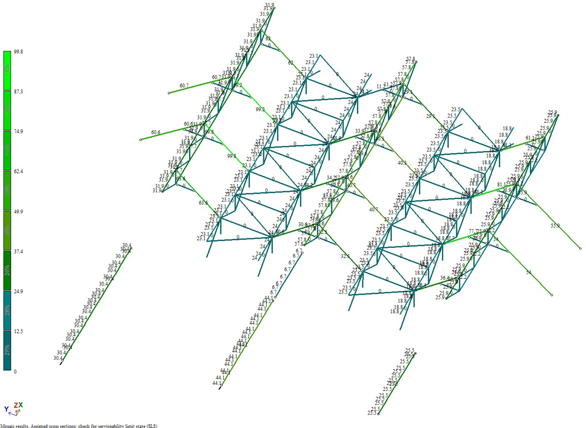
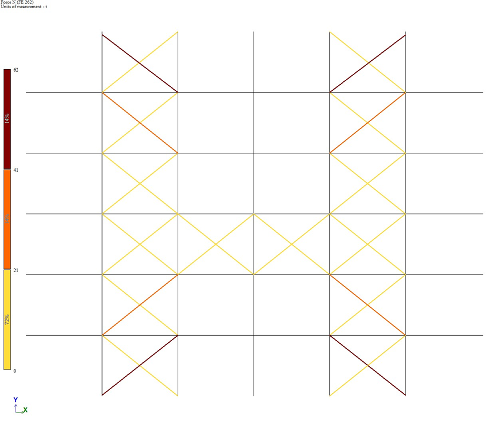
Local model issues were refined in LIRA-FEM, and three different models were created for nonlinear analysis by ULS, SLS Characteristic and SLS Quasi-permanent. Nonlinear tension-only elements were also used to model braces that work only in tension
|
Load application
Permanent loads (LC1–LC7)
- LC1: self-weight of structures;
- LC2: permanent load on floor slabs;
- LC3: facade load;
- LC4: soil pressure.
- LC5: equipment load
- LC6-LC7: load from the retractable grandstand (2 cases)
Imposed loads (LC9–LC12)
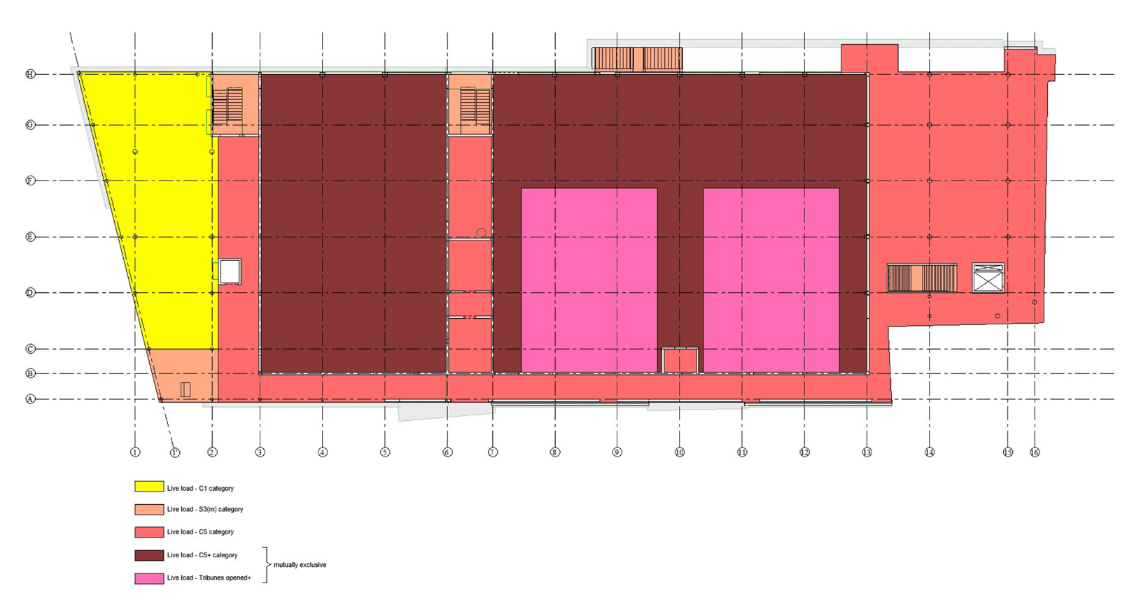
- LC9: loads according to the intended use of the premises;
- LC10: loads from internal partitions, equipment, etc..
- LC11-LC12: load from the retractable grandstand (2 cases)
Climatic loads (LC13–LC18)
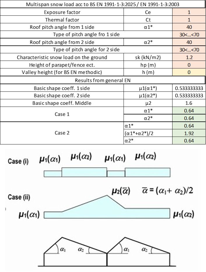
- LC13-LC14: snow loads (2 cases + snow drifts);
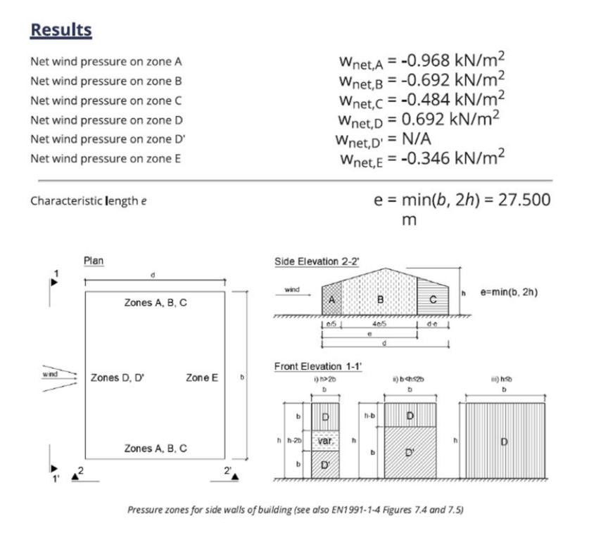
- LC15–LC18: wind loads in four directions (X+, X–, Y+, Y–).
3.1 Snow
|
3.2 Wind
|
Load combination tables were generated automatically. The safety factors for variable loads were changed from 1.5 to 1.3 in accordance with the Lithuanian National Annex to Eurocode LST EN 1991-1-1. The dynamic effects that may occur in the grandstand area were also taken into account
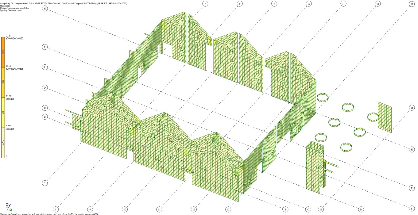 |
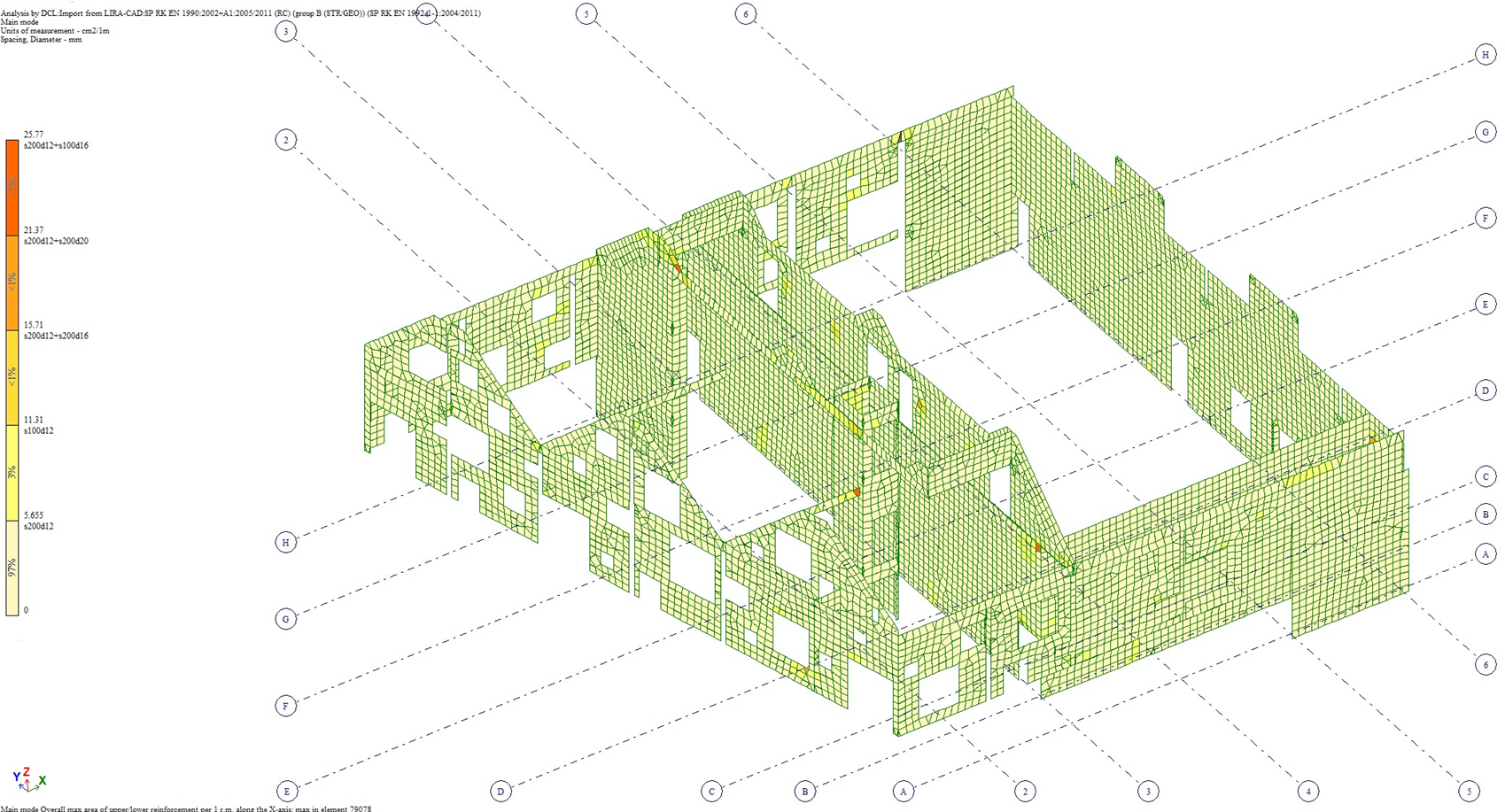
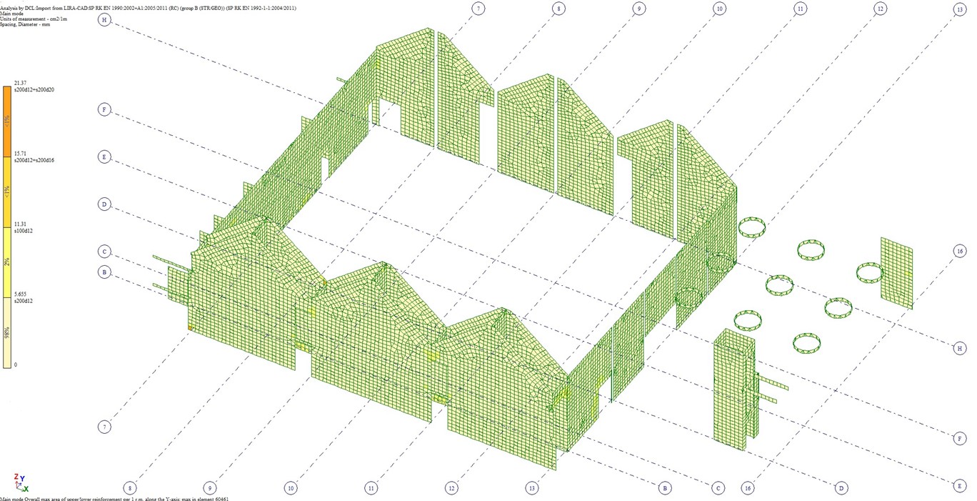
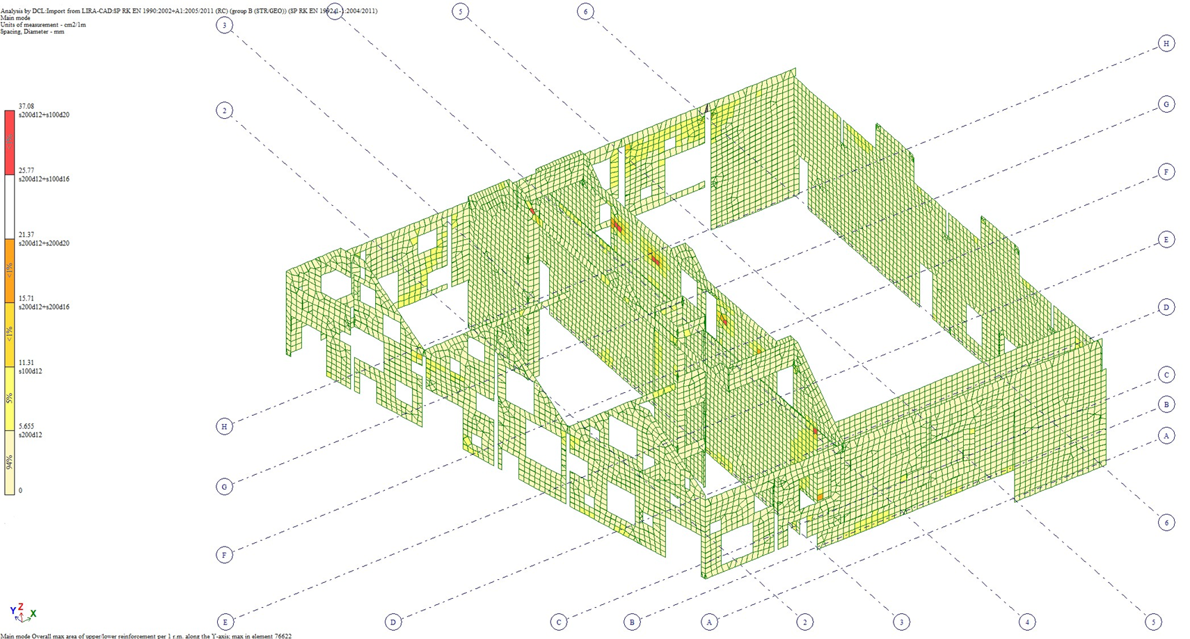
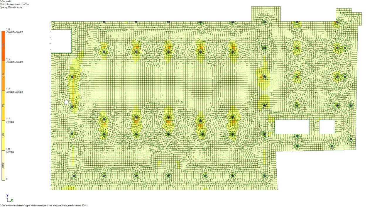
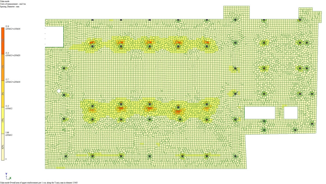
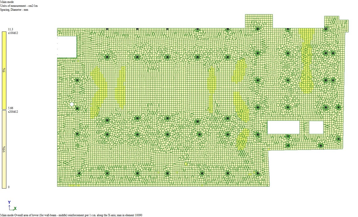
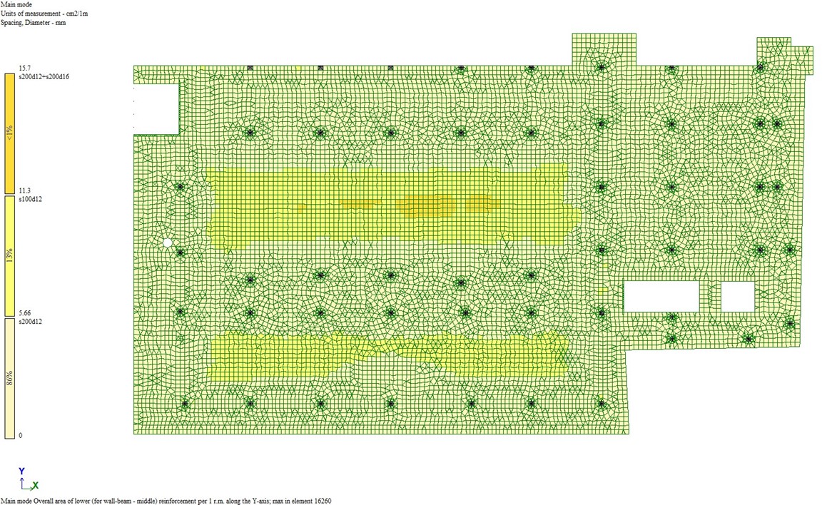
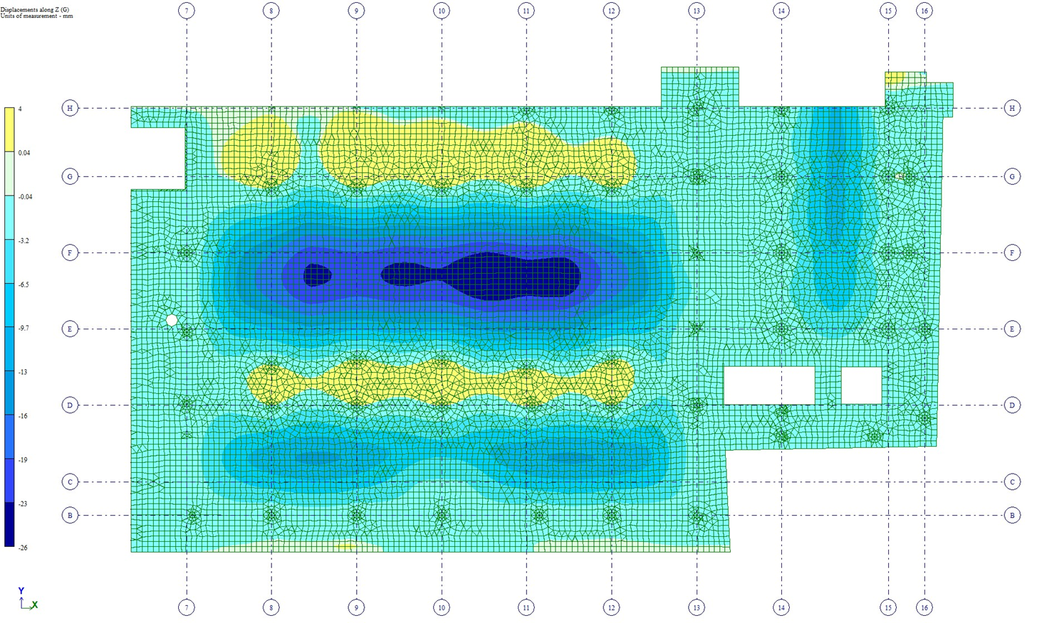
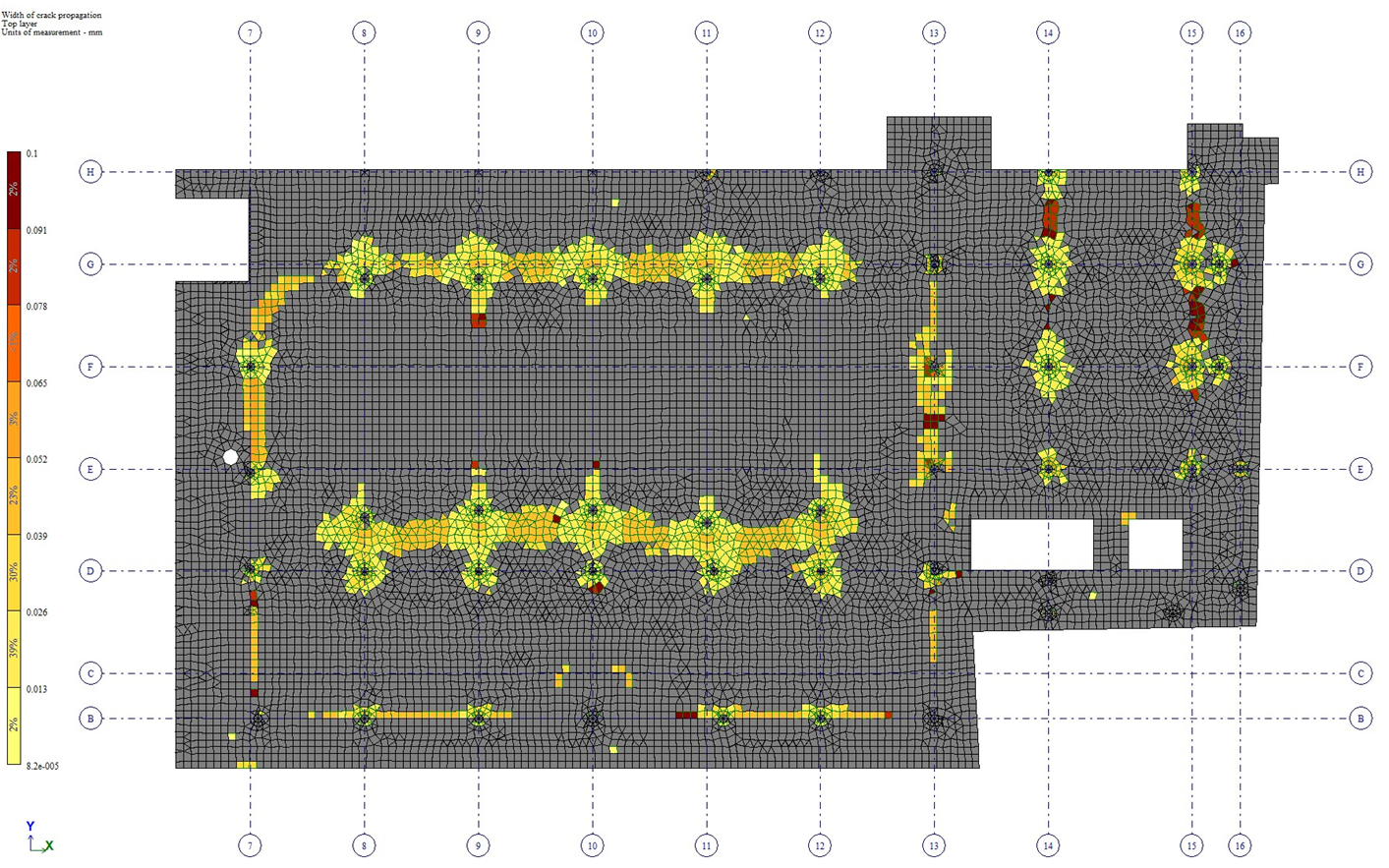
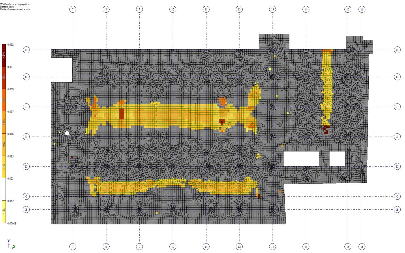
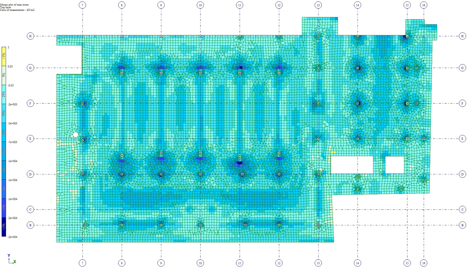
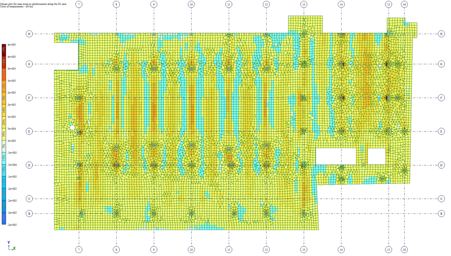
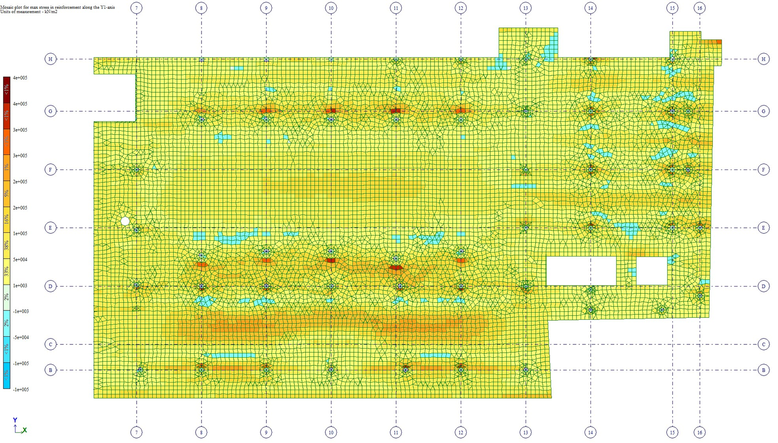
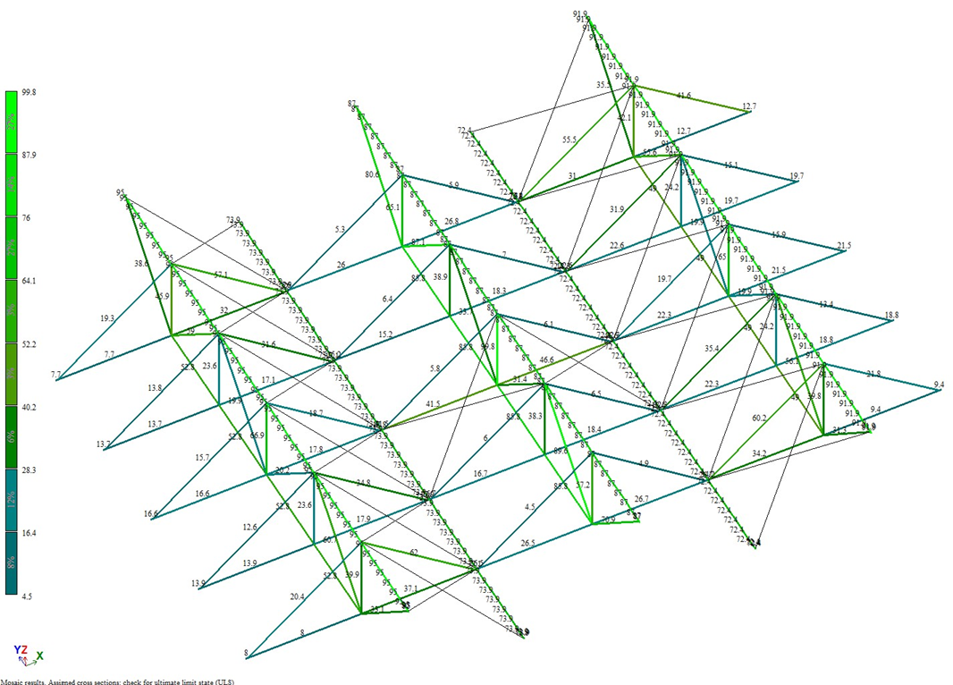
5. Analysis results: horizontal wall reinforcement.
|
|
|
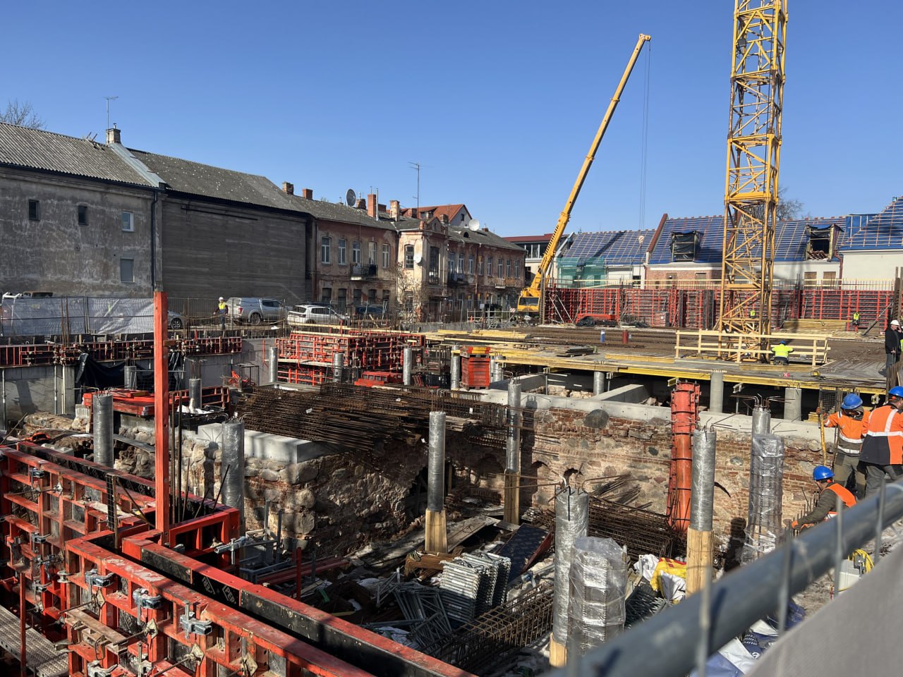
Construction process

Evaluate the software
If you have any doubt, download the Demo version and evaluate the program or contact our Support Team for more details.
Comments