Hydroelectric power station Boguchanskaya
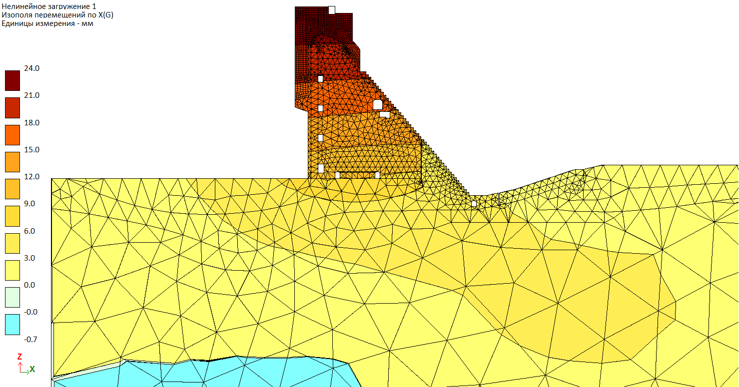
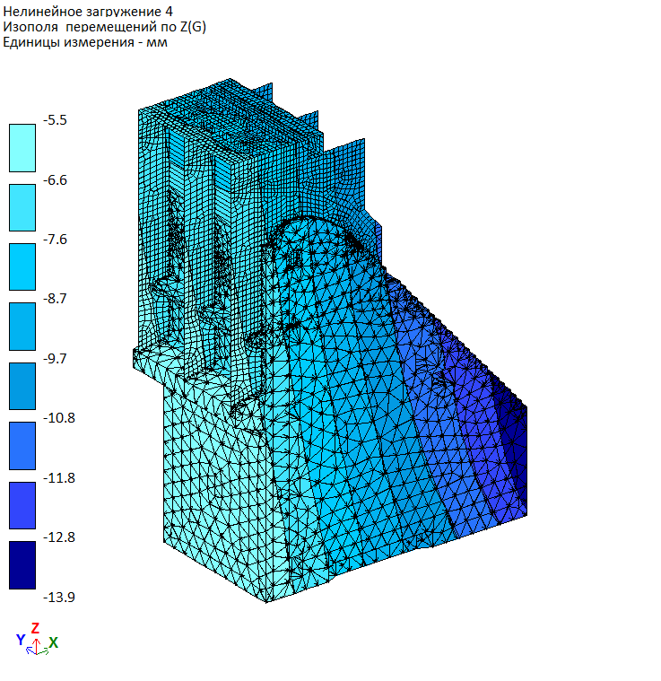
Spillway No.2. The stress-strain state, strength and stability analyses for the section No.21 during flood routing. Analysis of water cushion.

Design model: Gorodetsky` design bureau
Complete name for the project
Spillway No.2. The stress-strain state, strength and stability analyses for the section No.21 during flood routing. Analysis of water cushion.
Description
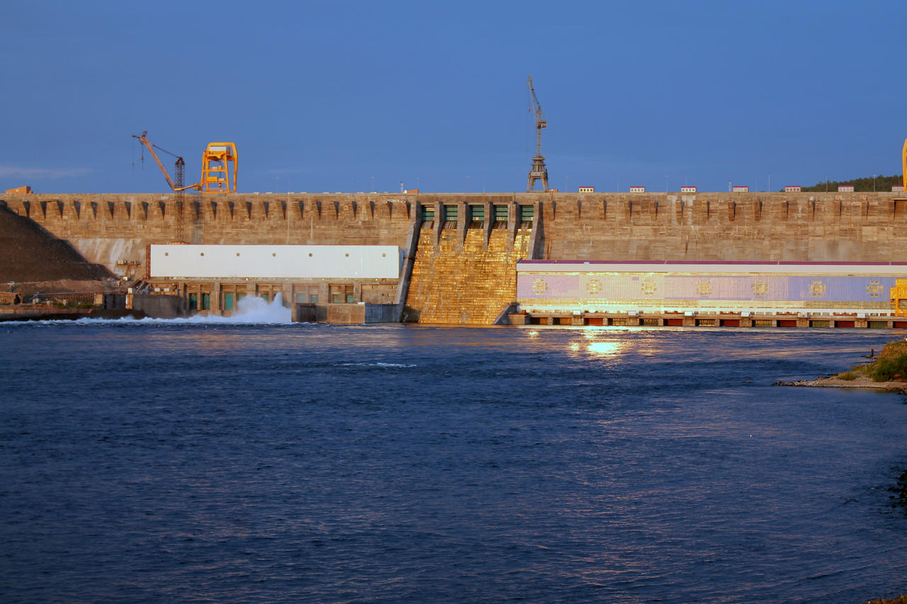
Boguchanskaya hydroelectric power station is located on the Angara river, near Kodinsk city (Kezhemsky region, Krasnoyarsk Territory). This station is included into Angarsk cascade of hydroelectric power stations; it is its fourth, the lowest level.
Peculiar feature
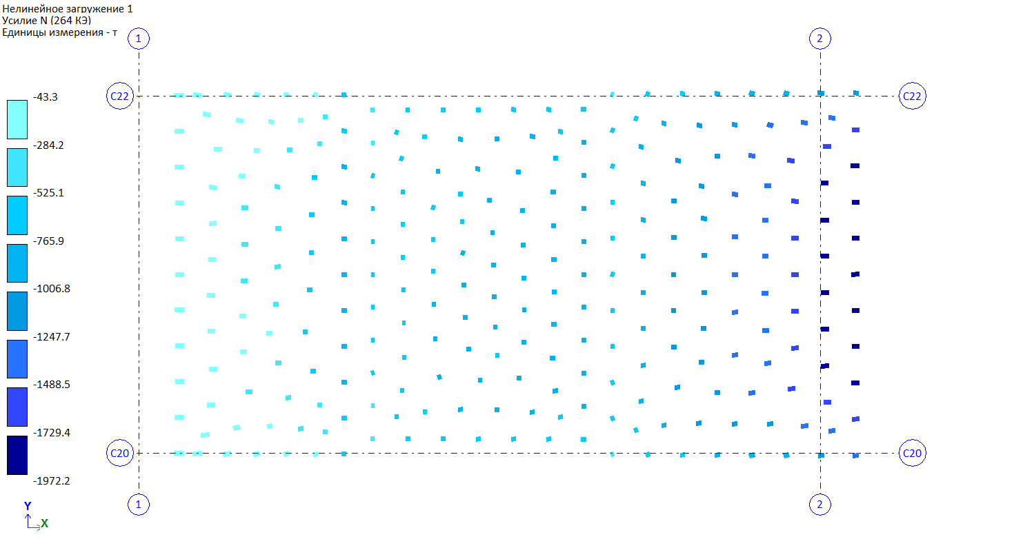
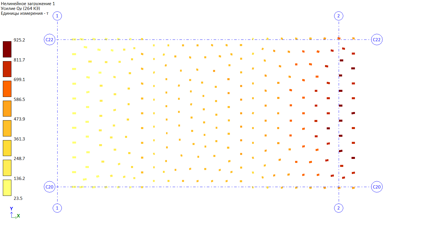
Dam base is simulated with special FE – one-way FE of friction.
Design model
The spillway section No.21 has width of 30m, two spillway spans with clear width 10m. This section is located in the channel part of the concrete gravity dam on rocky base. It is the central section of the spillway No.2 (sections No.No. 20-22 with total length of 90m).
Section No.20 (extreme left section of the spillway No.2) is adjacent to section No.21 to the left of the stream. Section No.20 is asymmetrical relative to its longitudinal axis; it has one spillway span with clear width 10m and blank section. Section No.22 (extreme right section of the spillway No.2) is adjacent to section No.21 to the right of the stream. Section No.22 has typical solution as the section No.21 (except the spillway guide wall on section No.22 - right-bank abutment of the spillway No.2).
Station sections No.No.11-19 (total length 270m) are adjacent to the spillway No.2 from the left side while blank section No.23 (width 22m) and then sections No.No.24-28 of the spillway No.1 (total length 110m) are adjacent to the spillway No.2 from the right side.
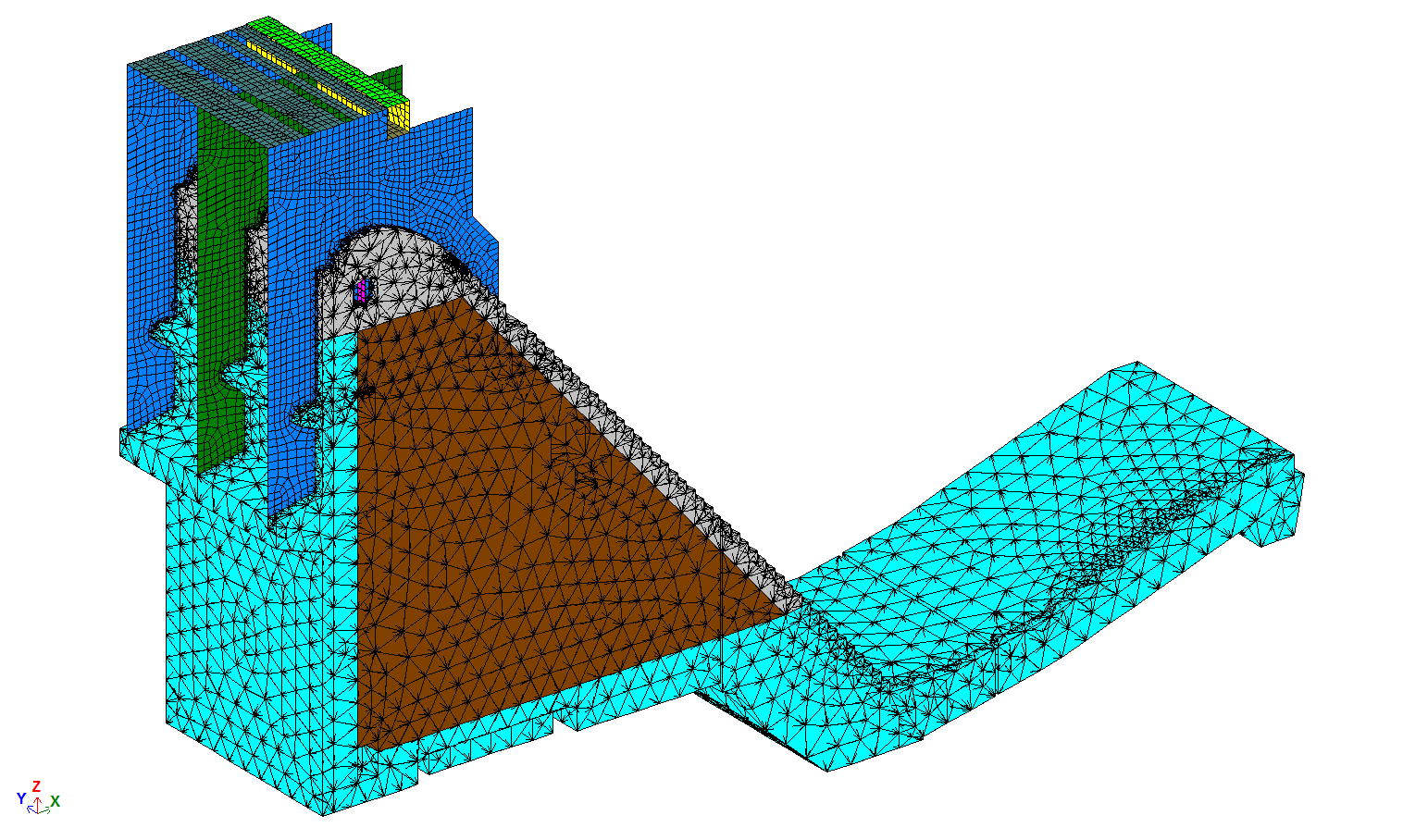
In section No.21 there are three piers: extreme left-bank and right-bank with thickness 3.0m (at gate slots with depth 0.9m, thickness of pier is reduced up to 2.1m); and central pier with thickness 4.0m (at gate slots 2.2m).
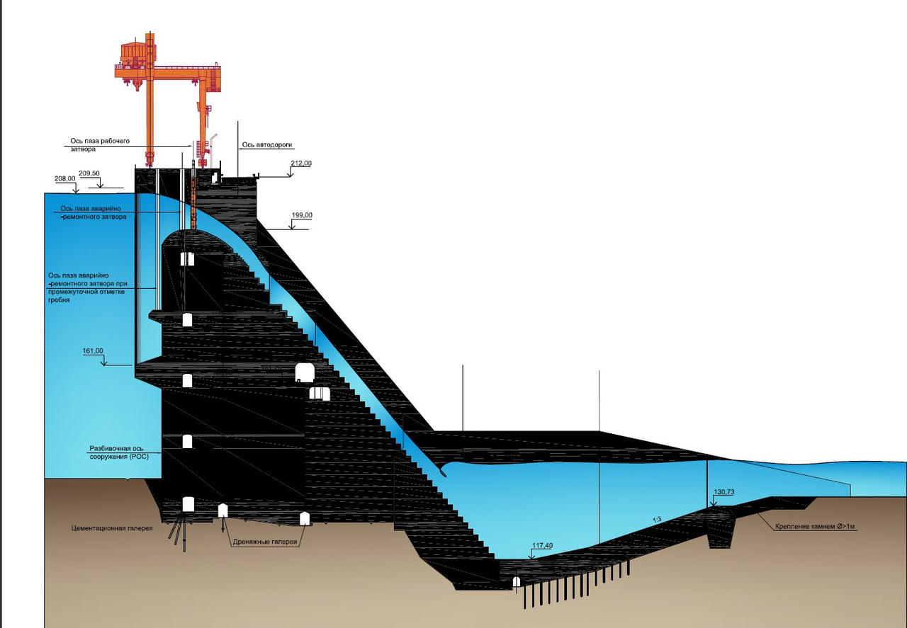
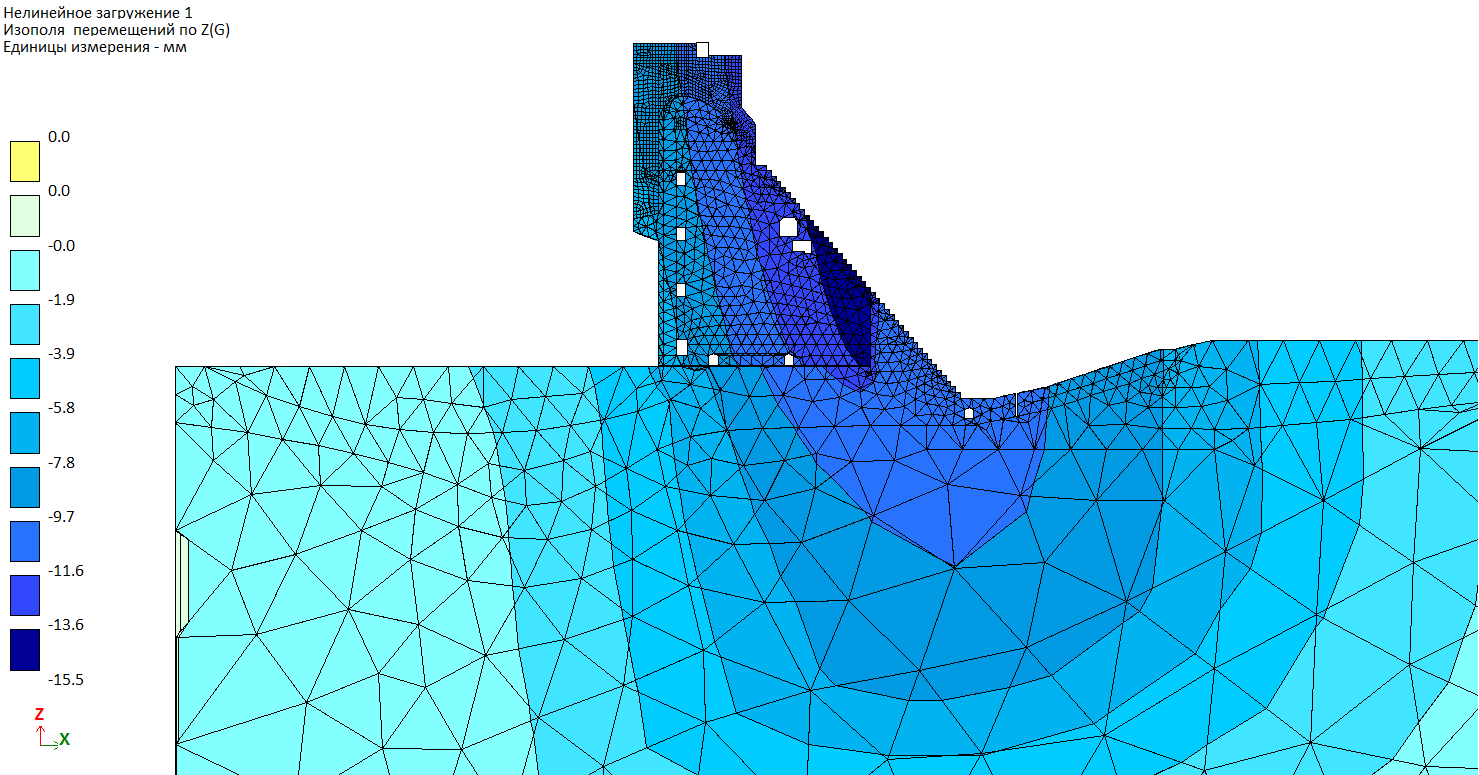
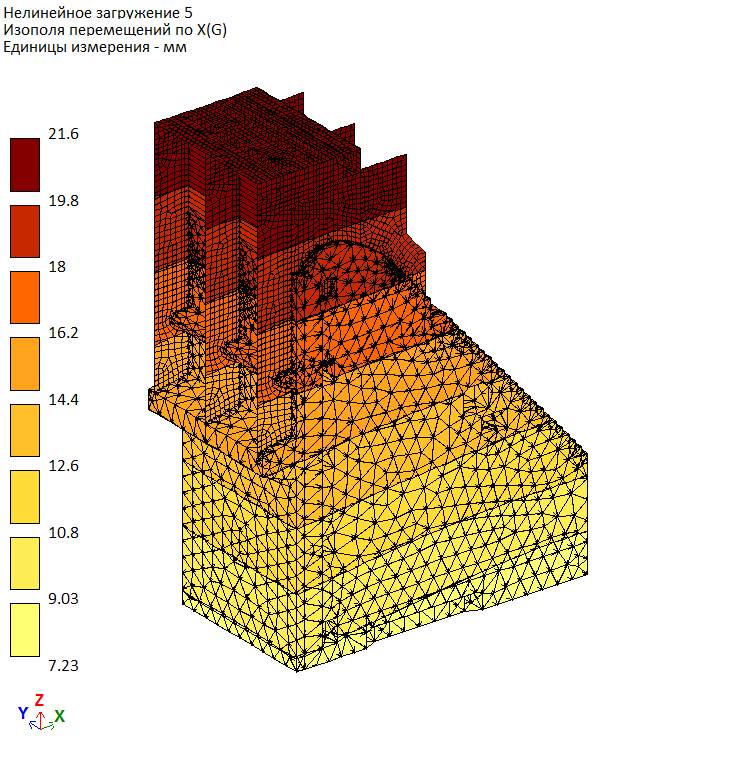
From the downstream side the piers function as bridge supports. Below the level 196.00 the piers has ledge to the downstream water beyond the bridge size; it is designed from hydraulic reasons (for water aeration, etc.). 3D FE model of the system - section No.21 'rock base' is presented in Fig.1.1-1.3 (at the stages of maintenance and start-up work). Presented 3D FE model provides the possibility to consider erection of section and filling of reservoir in two stages:
- for the first stage - filling the reservoir with a temporary elevation of the spillway crest 179.00m;
- to the design mark of filling the reservoir - up to elevation of the spillway crest 199.00m when previously built pier is concreted into the massive concrete of the spillway head.


Evaluate the software
If you have any doubt, download the Demo version and evaluate the program or contact our Support Team for more details.
Comments