Eurocodes in Practice: Structural Design of a Residential Building Using LIRA-FEM
This case study demonstrates the application of Eurocodes in the structural analysis and design of a multi-storey residential building in Vilnius using the LIRA-FEM software suite. The full design workflow is presented, including BIM/IFC integration, load definition and combinations, reinforcement design analysis, and the generation of an IFC reinforcement model for BIM coordination.

Developers: NJ Optimal, Lithuania
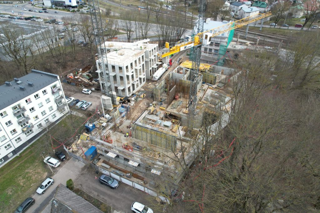
The designed facility is a building with an attic floor and a three-level underground parking garage.
The underground part of the structure is formed by reinforced concrete pile walls.
Plan dimensions are 67.0 × 40.0 m and 25.0 × 27.0 m.
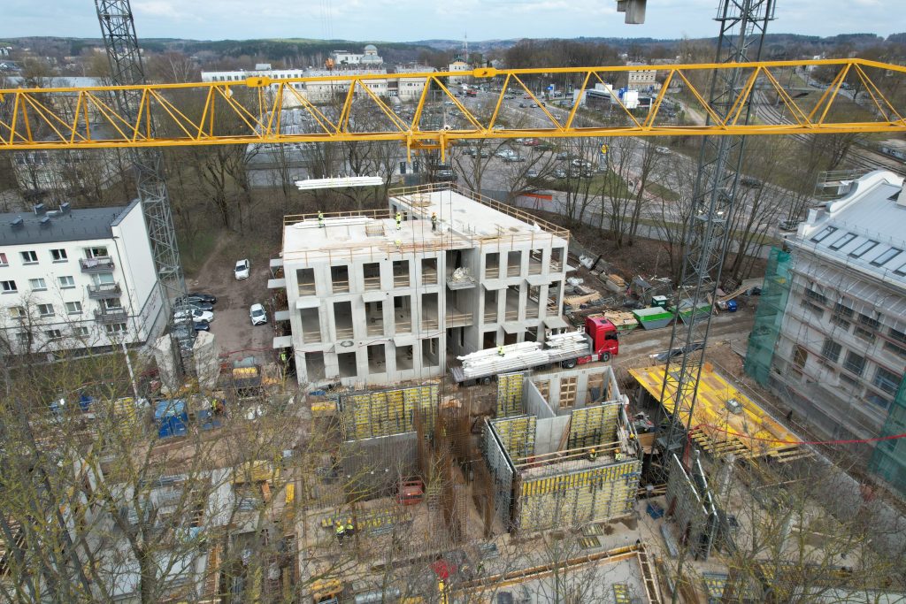
The height of the three underground parking levels is hₚ = 3.25 m; the height of the above-ground floors (levels 1'4) is hₐ = 4.8 m.
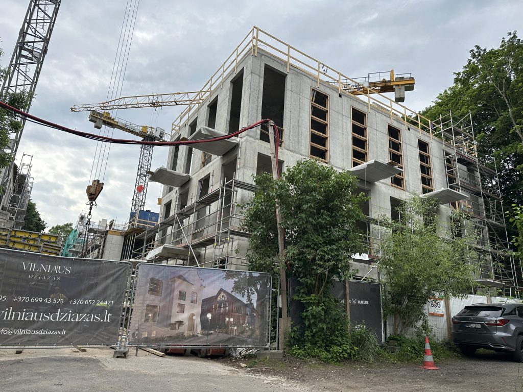
The total height of the building above ground level is H ≈ 19.0 m.
The building is divided by expansion joints at floor levels into deformation blocks; the maximum distance between joints is L = 35 m.
The blocks are connected by an underground tunnel.
Structural system: monolithic reinforced concrete foundations on bored piles with pile caps.
The perimeter of the underground part is formed by pile walls.
Monolithic reinforced concrete plinth beams; walls of staircases and elevator shafts; columns; floor slabs
(beam-and-slab systems are used in zones with high loads).
Reinforced concrete elements were analyzed and designed using reinforced concrete design software integrated within the LIRA-FEM computational environment.
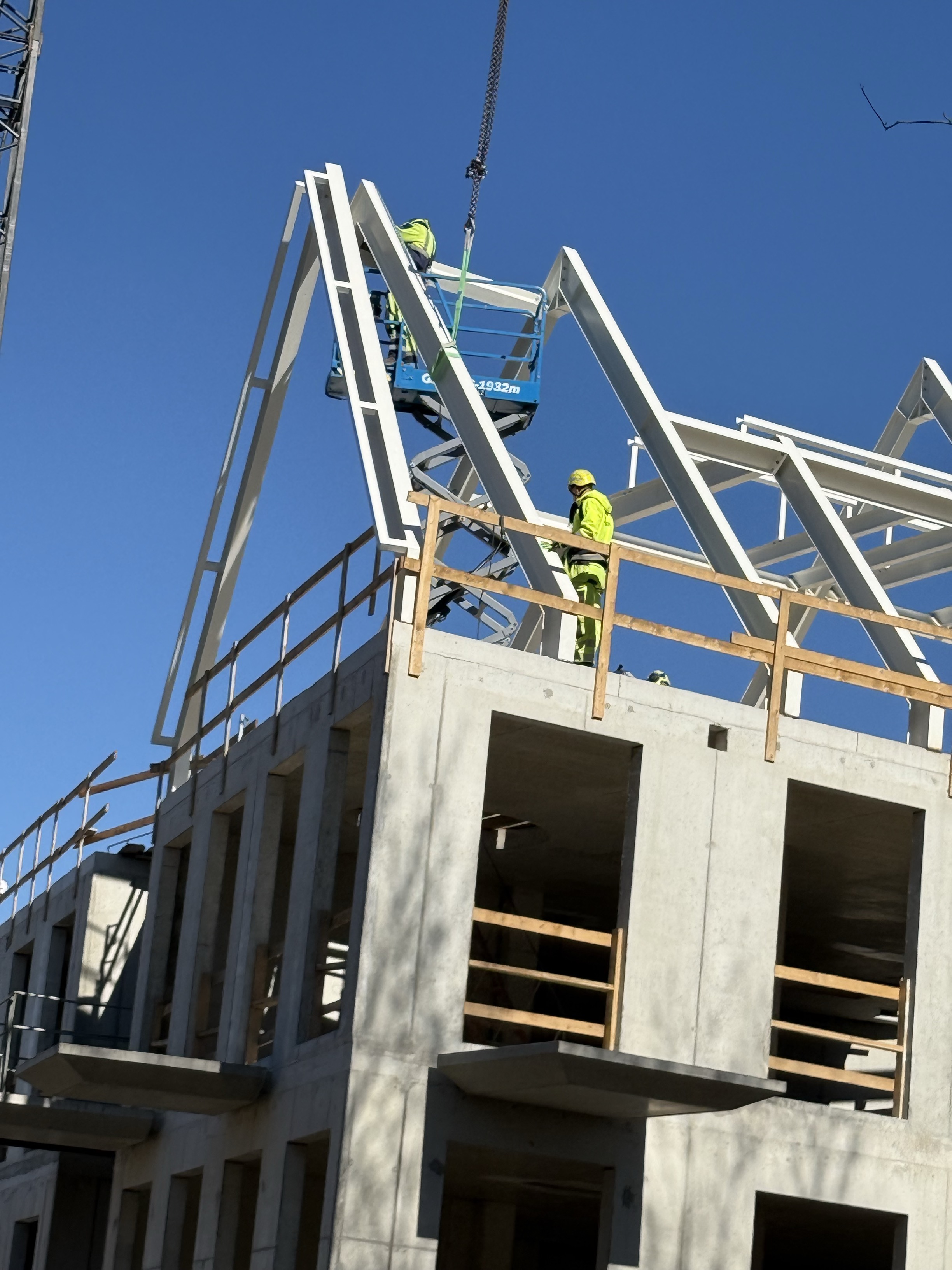
Pitched roofs are supported by steel trusses.
Slabs are rigidly connected to columns and walls.
Columns are monolithic reinforced concrete.
Staircase walls and elevator shafts are flexibly connected to the foundations.
Steel beams are hinged to reinforced concrete structures.
Bored piles are used.
During foundation construction near streets and existing buildings, temporary ground support measures are provided.
The prepared IFC model from Revit was imported into LIRA-CAD (SAPFIR 3D 2024) and subsequently refined.
Geometrical inconsistencies were corrected, and slab and wall thicknesses were adjusted
through several iterations in order to achieve optimal structural solutions.
Load combination tables were generated automatically.
Additionally, safety factors for imposed loads were adjusted from 1.5 to 1.3
in accordance with the Lithuanian National Annexes to Eurocode LST EN 1991-1-1.
Below are examples of reinforcement design results for walls and slabs in Sections A and B.
Navigation
Project overview
Project description
Key parameters
Main design solutions
Stages of the structural model development
IFC import and BIM integration
")
Load application
Permanent loads (LC1'LC4)
Imposed loads (LC5'LC6)
Climatic loads (LC7'LC11)
Load combinations (ULS/SLS) and national annexes
")
")
Calculation results
")
")
")
")
")
")
")
")
")
")
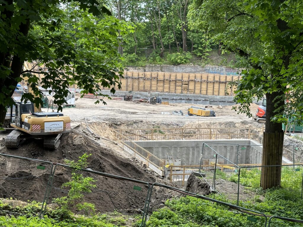
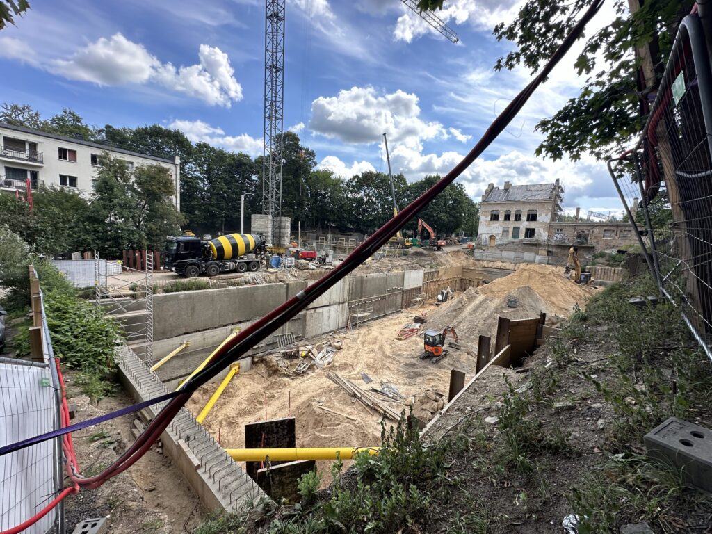
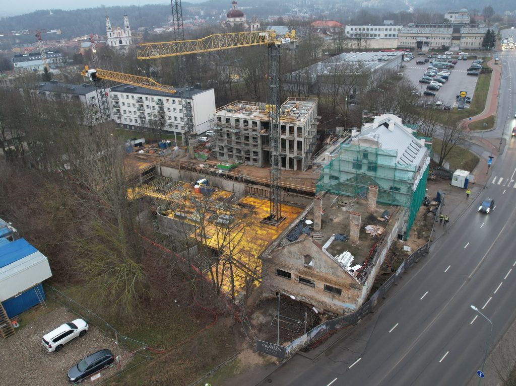
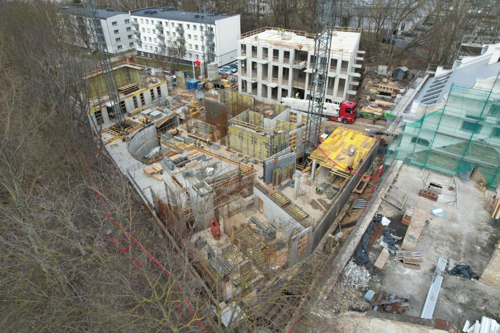
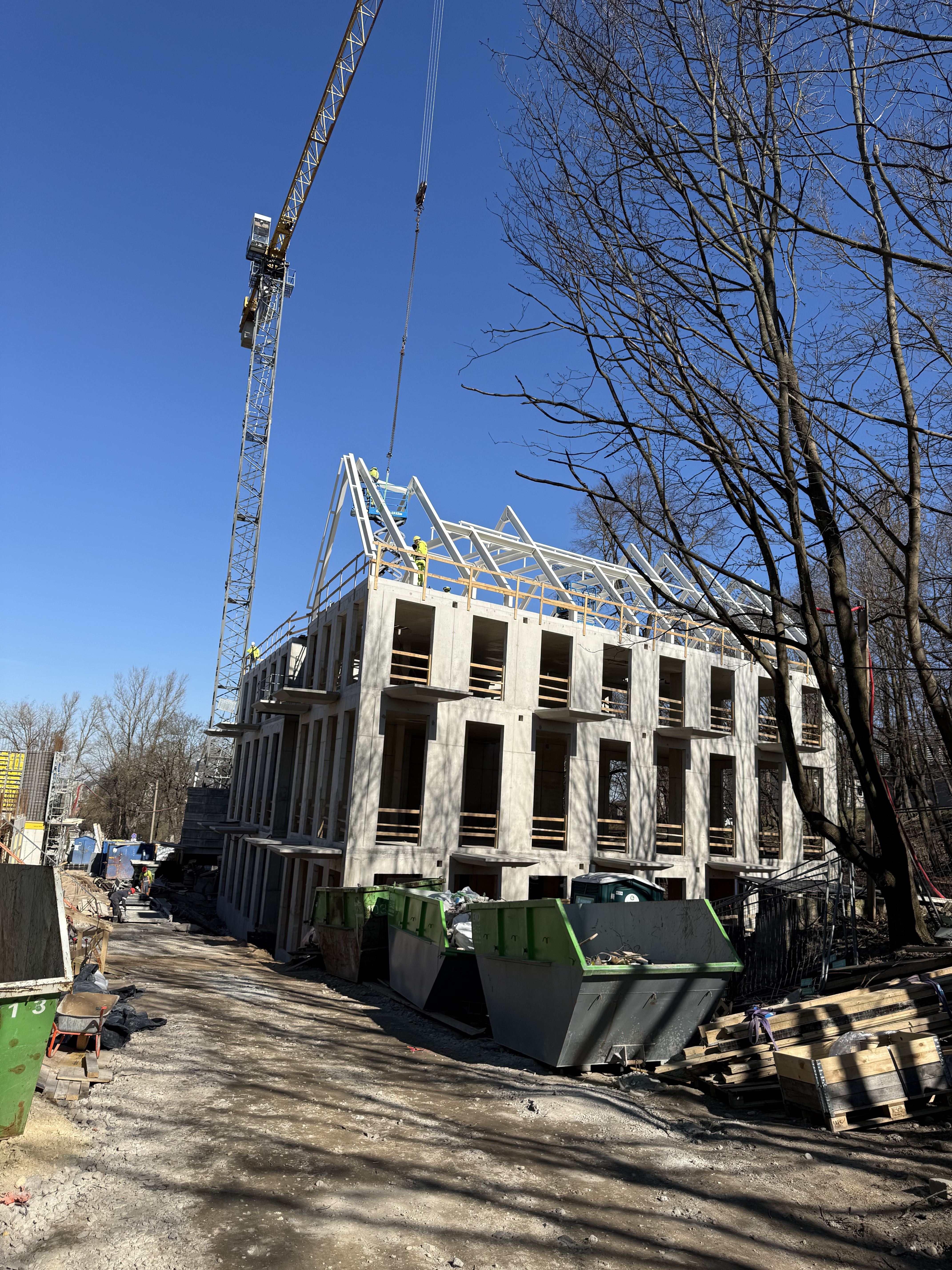
Construction process


Evaluate the software
If you have any doubt, download the Demo version and evaluate the program or contact our Support Team for more details.
Comments