LIRA-SAPR 2022 R2 Release Notes
Structural engineering software LIRALAND Group
Interoperability - components of BIM technology
-
Improved plug-in Revit - LIRA-SAPR:
- the 'Export' dialog box is now non-modal, so it is possible you to assign properties to Revit analytical models without closing the dialog box;
- restored option to export the Linear load to the element from Revit 2022 to LIRA-FEM program;
- new option to assign 'materials by category' for the English localization of the program.
-
Combined
*.dwgand*.dxfimports for the 'Import floor plans', 'Import AutoCad drawing', 'Import model to new project' commands and for the 'Import underlay in*.dxf,*.dwgformat' node. - In the 'Import floor plans' dialogue box, the storey height may be saved to the parameter template to be applied later.
-
Enhanced import of IFC:
- storeys are created by slabs for models that are saved in the IFC as one storey;
- improved recognition of walls with a large number of faces;
- improved recognition of openings;
- new recognition of object colours;
- improved import of beams.
SAPFIR-Structures
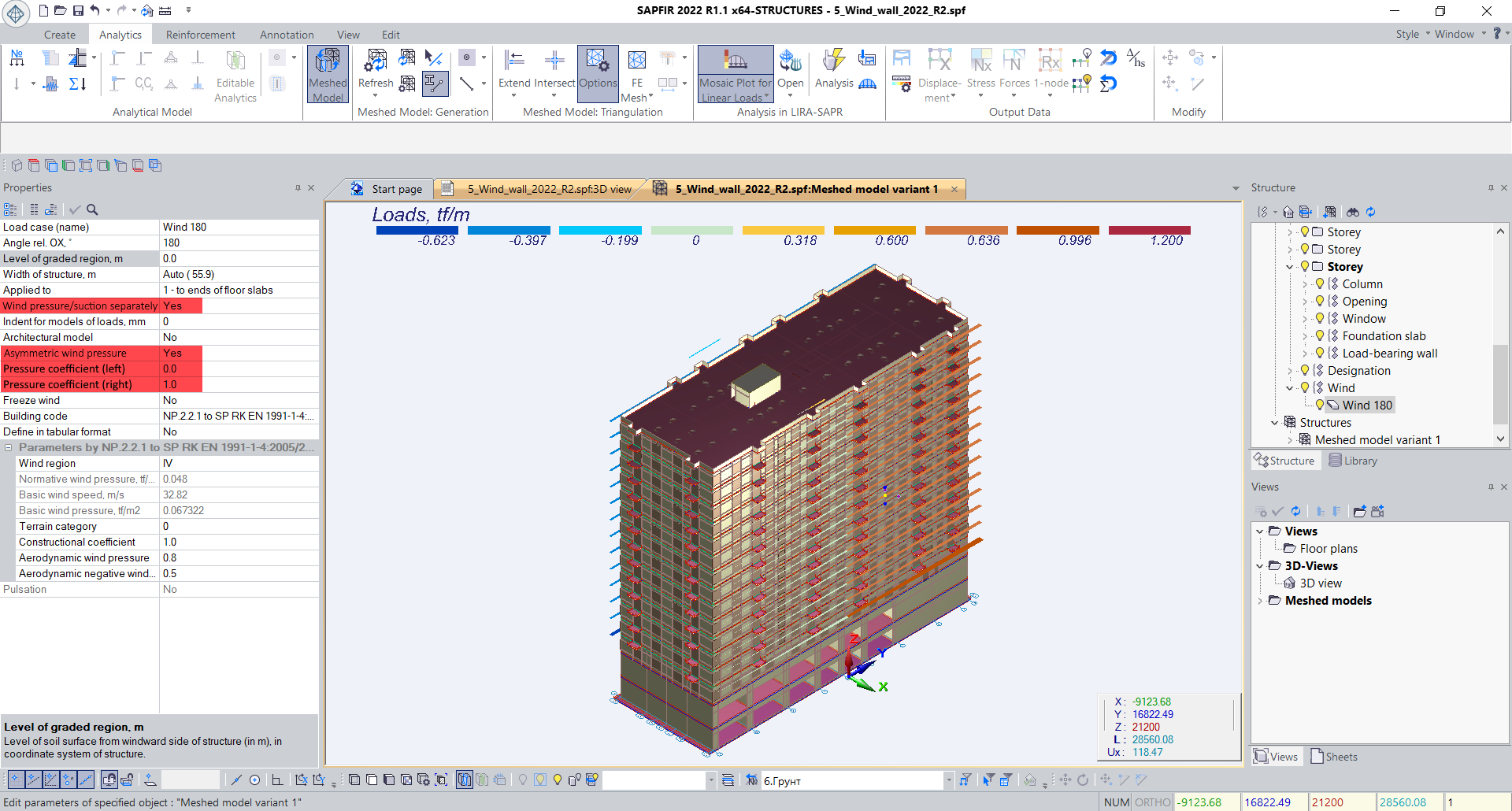
- If the wind load is applied by method '1 - to ends of floor slabs', the pressure/suction option is implemented separately (for all building codes). If the option is defined as 'Yes', then the separate loads are generated for the positive and negative wind pressure.
- SP RK EN 1991-1-4:2005/2011 Wind loads, clause 7.1.2 (Asymmetric wind pressure) is supported. If the wind load is applied by method '1 - to ends of floor slabs' and '2 - positive/negative wind pressure', it is possible to define the parameter 'Asymmetric wind pressure' with pressure coefficients (left/right) for all building codes.
- In the 'Sum up loads' dialog box, there is new option to edit the total load separately for each direction and for each load case. This option is available in the 'Architecture' and the 'Meshed model' modes.
- New modules for earthquake loads according to building codes of Uzbekistan KMK 2.01.03-19 (module 33), Tajikistan MKS CHT 22-07-2007 (module 48) and Georgia PN 01.01.-09 (module 53).
- The following parameters are added for all earthquake modules:
- the required percentage of modal masses;
- option to sum up the displacements with the same frequency;
- option to define the method for summing up the earthquake components;
- account of excluded and non-computed mode shapes.
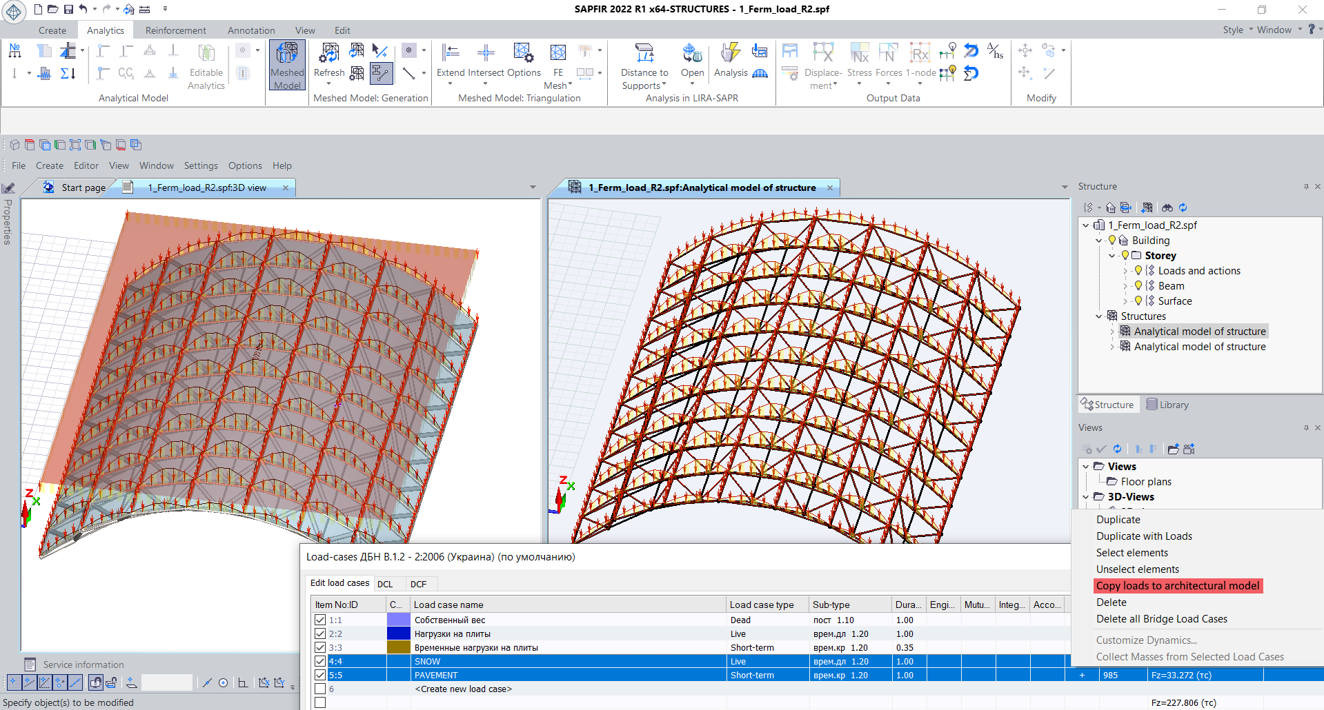
- In the 'Meshed model' mode, the 'Copy loads to architecture' option is available in the 'Load cases' dialog box, on the 'Edit load cases' tab (see the shortcut menu). It enables the user to copy any loads to architecture, including wind loads and loads obtained after the load collection with proxy objects.
-
Option to delete the load case together with all loads it contains:
- for wind, earthquake, special load and soil pressure - the relevant items are deleted in the 'Structure' window;
- for the load defined in the properties of slab - the relevant item with the load value becomes clear;
- for objects with interpretation 'Load' (partition, beam, column, slab, etc.) - the object itself is deleted.
- A new triangulation method 'adaptive quadrilateral version 2' is implemented. Based on comparison results, for certain problems, the 'adaptive quadrilateral version 2' method may speed up the process by 2 to 4 times. The greater the ratio of model dimension to triangulation step and the more mandatory points for triangulation, the faster the triangulation will be with the new method relative to the previous method. Also for a number of problems in which the 'Smooth mesh' option enabled, the FE mesh quality is considerably enhanced.
Large Panel Buildings
- Enhanced division of the FE of joint over openings.
- Enhanced generation of embedded items in the joint over the openings in case the 'Lintel is simulated with bar' option is defined in the properties of the opening.
Design of RC structures (Reinforced Concrete)
- The drawings and detail views for punching shear according to the SP RK EN 1992-1-1:2004/201.
- A new 'Arrangement of reinforcement' dialog box is mentioned to define the parameters for the arrangement of transverse reinforcing bars in punching shear and then to design with separate rebars or reinforcing cages.
Generator
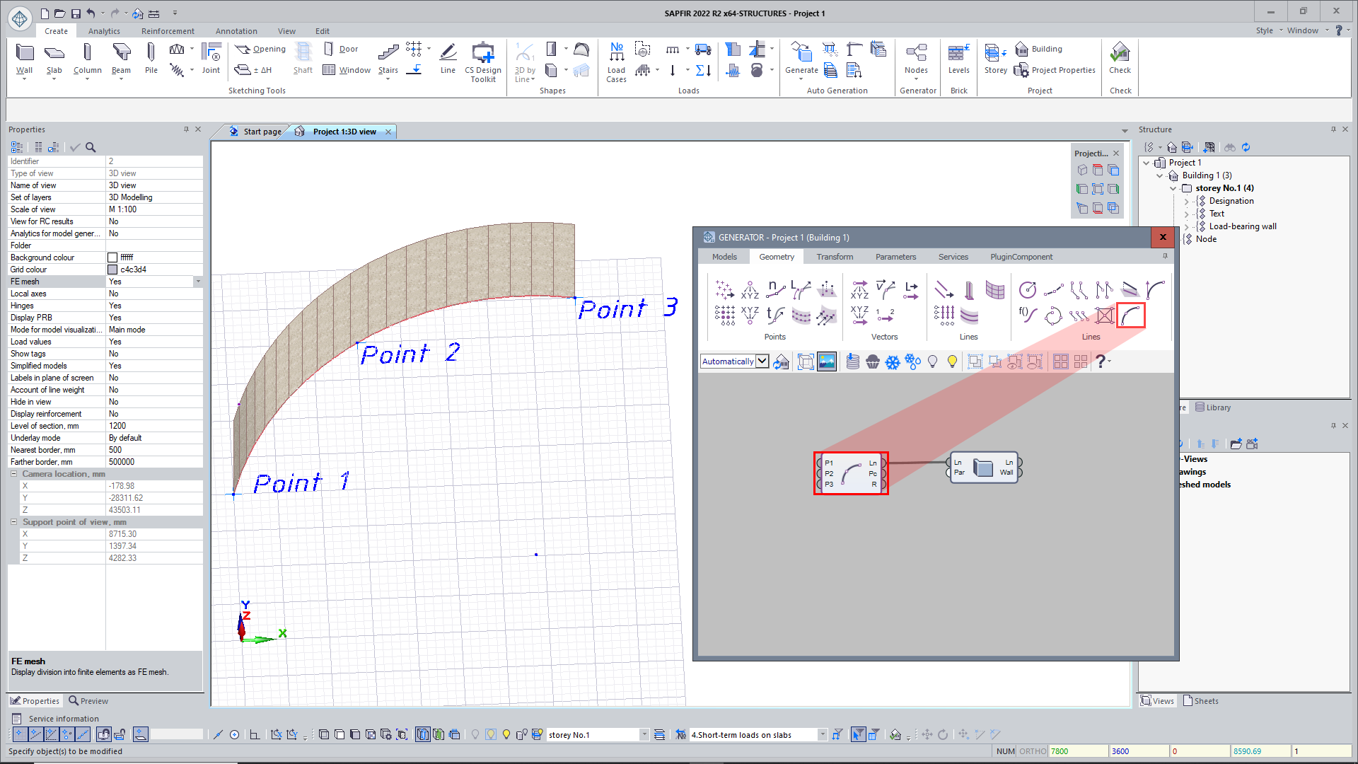
- Added nodes: 'Arc by three points', 'Arc by two points and direction', 'Plane by three points'.
VISOR-SAPR
- For EN 1990:2002+A1:2005, SP RK EN 1990:2002+A1/2011, it is possible to generate characteristic DCL(c) from the output data for time history analysis of the problem. With this option you could, for example, use the time history analyses for the design of active seismic insulation and at the same time to verify the load-bearing capacity of structural elements (reinforced concrete, steel).
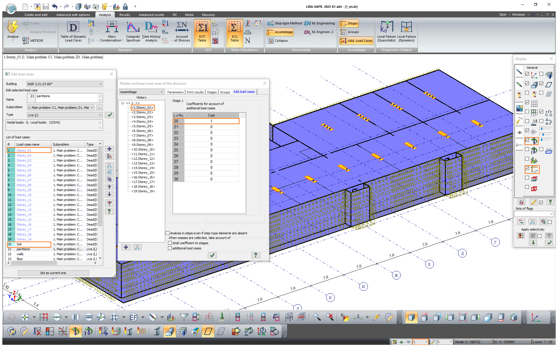
- Enhanced visualization of the model so that assemblage stages are displayed with account of additional load cases. When this option is enabled, not only the elements assembled at this stage are displayed, but also the additional load cases associated with this stage. Mosaic plots for loads and summing up the loads (additional load cases defined in the current assemblage stage are considered) will depend on whether this option is enabled or not.
-
For problems in which erection is modelled, new checks for the input data are added. In the 'Model nonlinear load cases' dialog box, there is new command to select the elements assembled (mounted) at the current stage with loads applied before assemblage.
-
New option to add the selected element to the list of elements that should be assembled or disassembled.
-
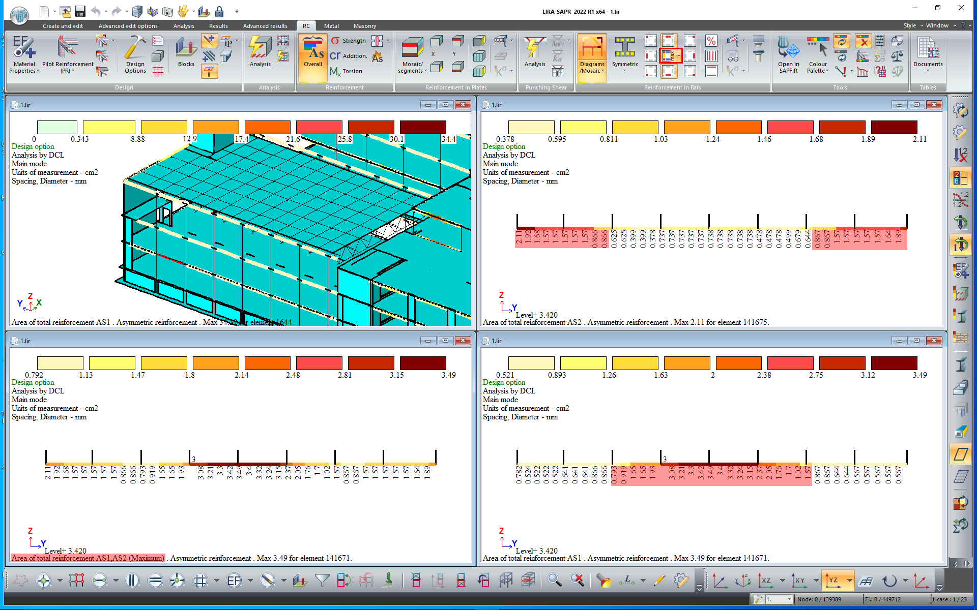
New option to display the mosaic plot for max area of longitudinal reinforcement at the corners/top and bottom faces/side faces of the bar section along the certain direction.
-
New mosaic plots for the output data from analysis of reinforced concrete (RC) structures:
-
codes for errors in calculation of seismic safety factors FS in bars and plates for DBN B.2.6-98:2009 'Concrete and reinforced concrete structures';
-
test perimeter Uout in punching shear according to SP RK EN 1992-1-1:2004/2011 'Design of reinforced concrete structures'.
-
-
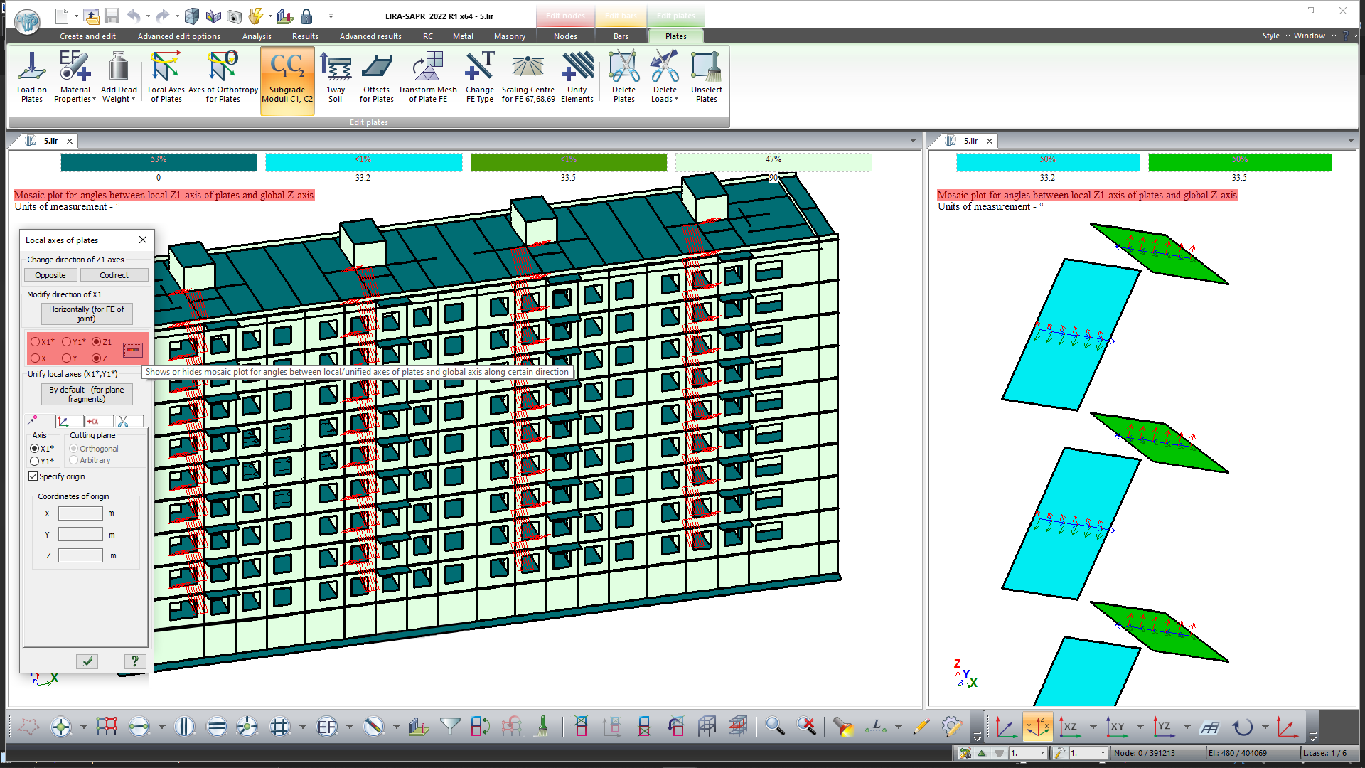
Mosaic plots for angles between the selected local (unified) axis/axis of orthotropy of the plate and the global axis.
-
New option to edit the surface loads in groups.
-
When perfectly rigid body (PRB) is generated, there is an option to convert selected PRB into bars of high stiffeness. This feature may be helpful when modelling thermal loads, e.g. for floor slabs to avoid stress concentrations at the slab-to-column connections.
-
Visualization of envelopes for max, min and max in absolute value of the examined parameter for nonlinear histories (without intermediate results) and crack parameters (with intermediate results).
-
Visualization of envelopes for max in absolute value (ABS) examined parameters for DCF and DCL characteristic.
-
When the coefficient for modulus of elasticity is defined, there is a new option to edit the coefficients (defined earlier) for the selected elements or for the whole model by a factor of n times.
-
In the 'Skews' dialog box, new behaviour coefficient q is added to calculate the sensitivity coefficient of storey skew in the earthquake design situation.
-
In the 'Design combination of loads' dialog box, there is a new option 'Replace types of load cases in the current DCL table with the data from the 'Edit load cases' dialog box'.
Important: When this command is activated, the DCL combinations defined earlier will be reset.
-
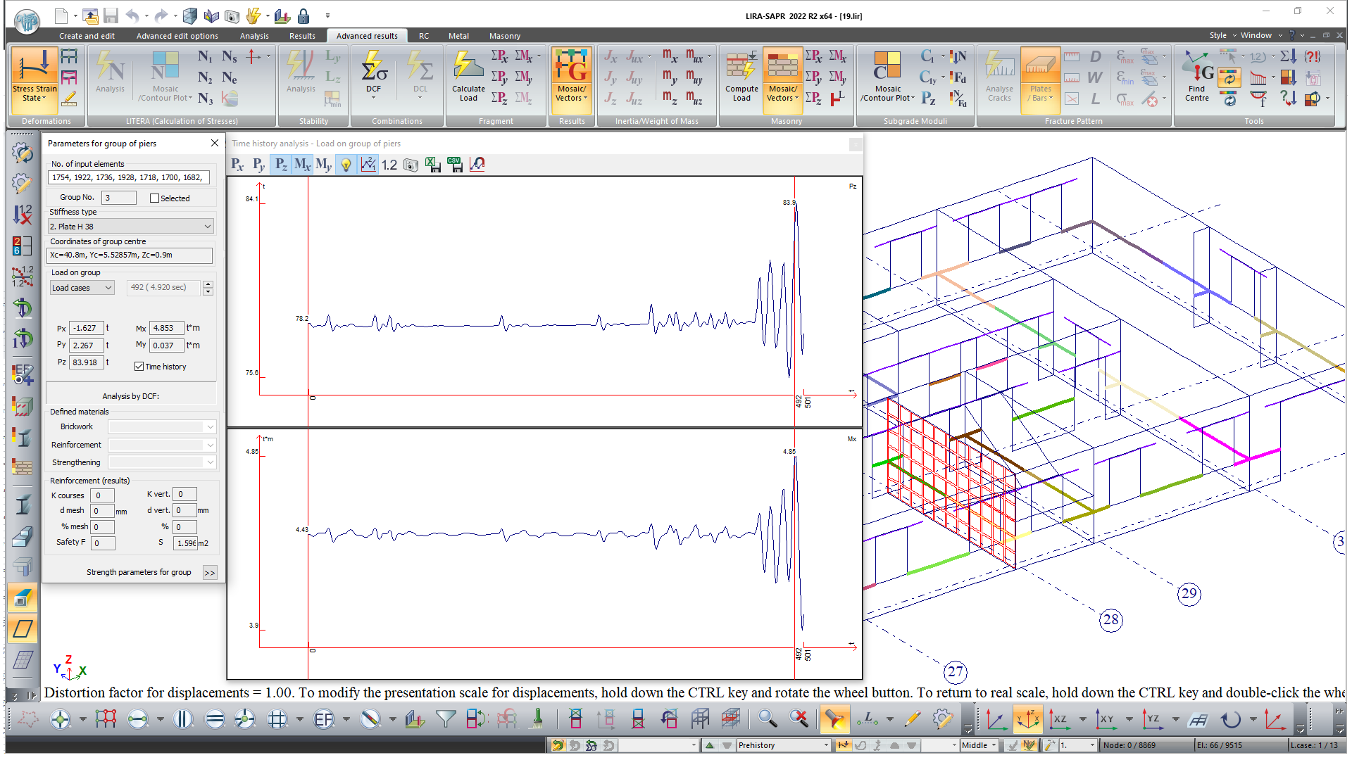
In time history analysis, the changes in reactions over time can be displayed graphically for the nodes where the load (reaction) on the fragment is calculated.
-
In the window with graphs for changes over the time, new command 'Bring to extreme values': displacements, forces, loads on a fragment, loads on a group of partitions, temperature and graphs of kinetic energy. When the 'Bring to extreme values' mode is activated and you add the check time points with the mouse pointer, the time point with the nearest local extremum will be assigned.
-
To consider the imperfections in complex structures, the strategy is to generate the initial geometry with curvature. A better selection of shape for the initial imperfections should replicate the global buckling mode. The current version implements a technology to update the model's geometry according to the results (displacements, mode shapes, buckling mode).
-
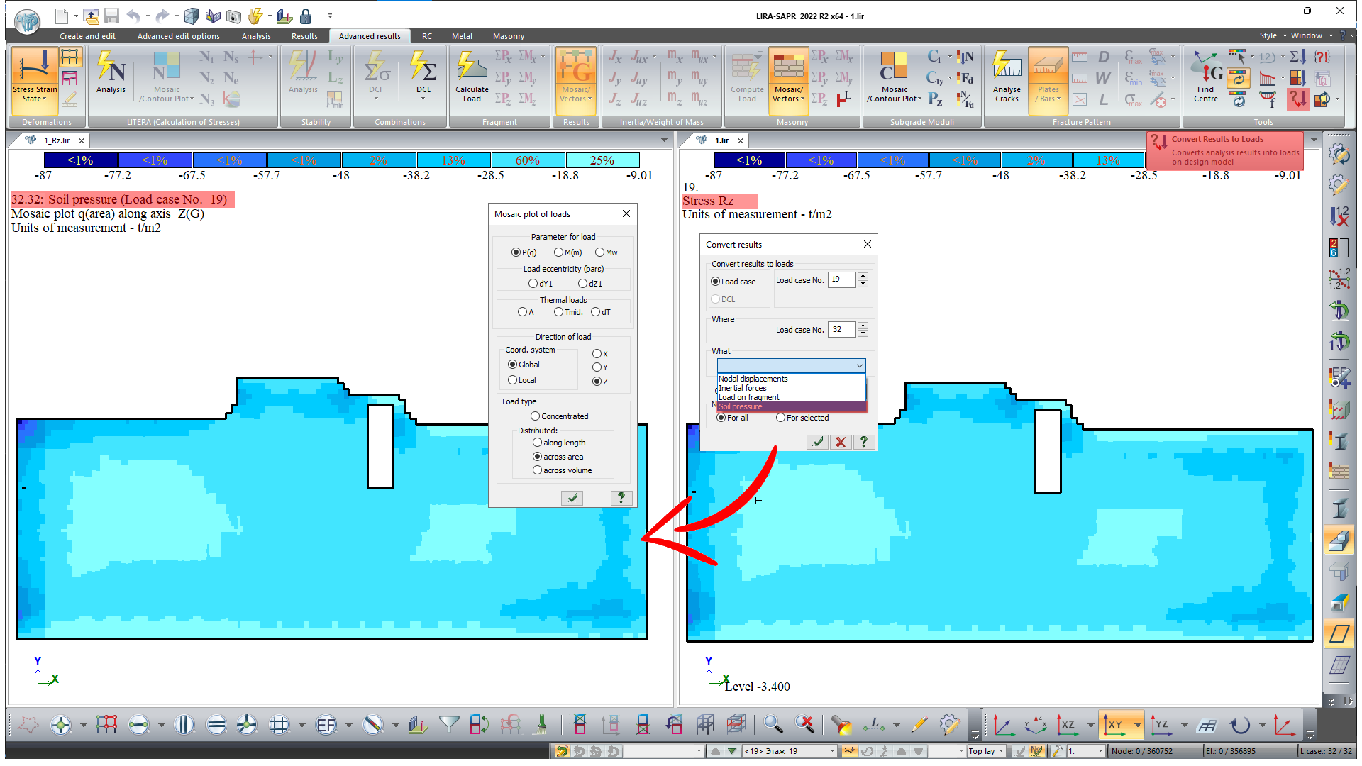
Option to convert the soil pressure into a static load.
-
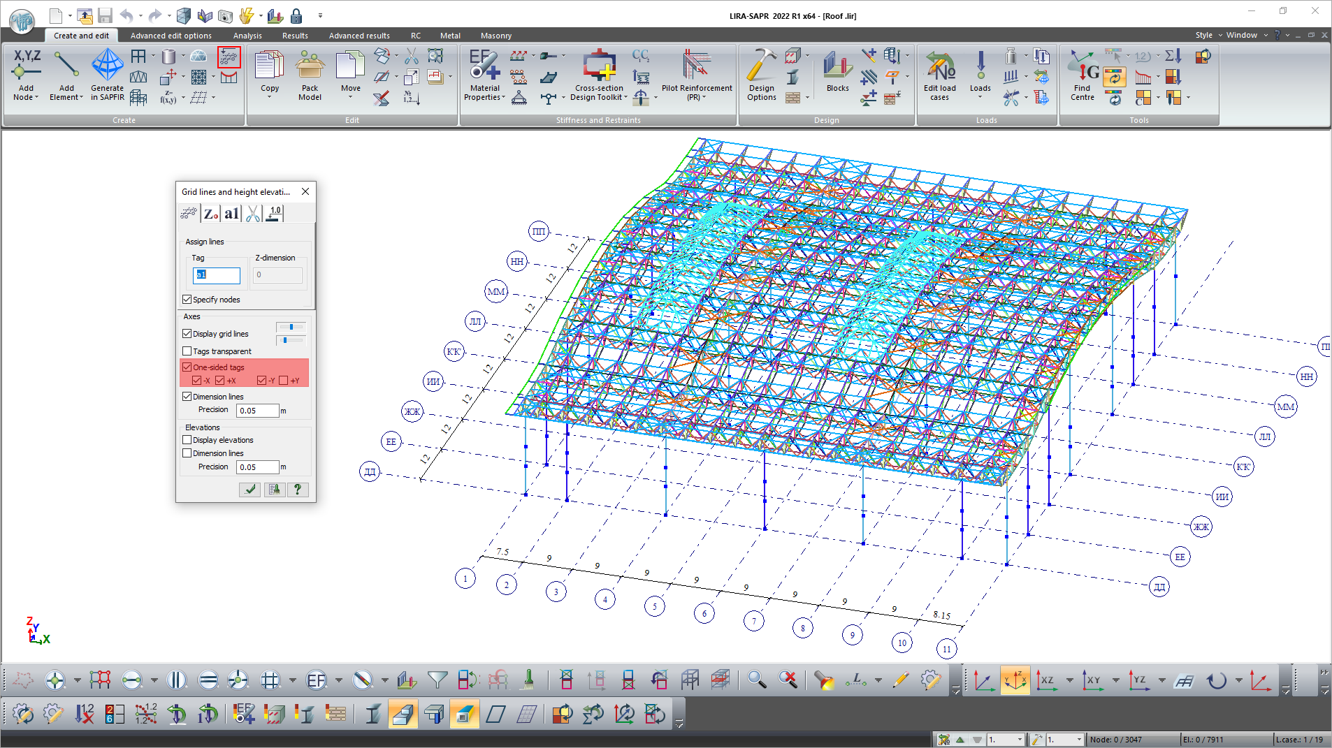
Option to define the side for presentation of grid line tags.
-
Option to automatically subdivide (along the vertical) the structural blocks of walls and columns with account of defined elevations.
-
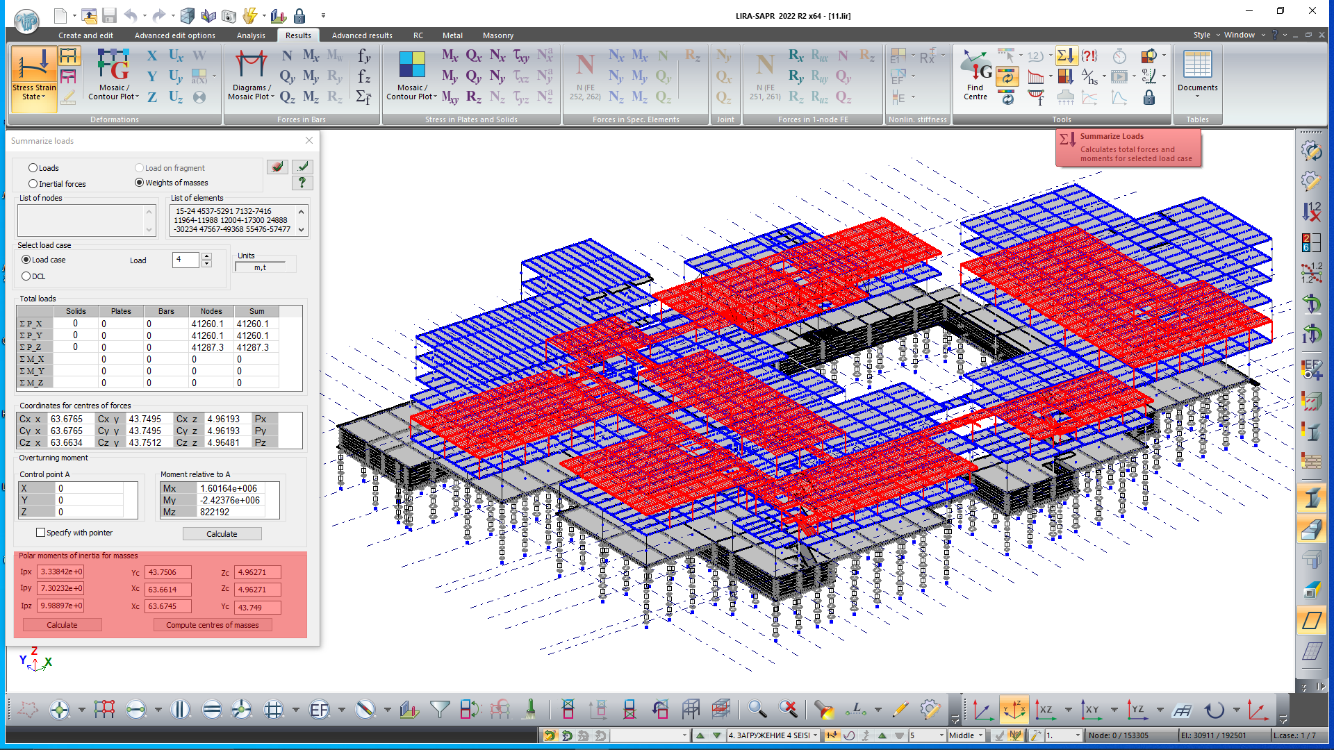
In the 'Summarize loads' dialog box, new option to calculate polar moments of inertia of masses both for the whole model and for an arbitrary fragment of the model relative to the calculated centres of masses or arbitrarily defined poles.
-
Option to recalculate the total and unit loads calculated on partitions (for cases when the group of partitions and/or design levels is modified after complete analysis).
-
Option to assign the damping ratio to elements of the design model and to visualize the mosaic plot for damping ratio.
By default, damping ratio for the elements are not defined (=0). It is possible to assign different damping ratio to certain elements. If the damping ratio is not assigned to some elements, then the value of the damping ratio defined in parameters for dynamic modules 27 and 29 will be applied in analysis.
-
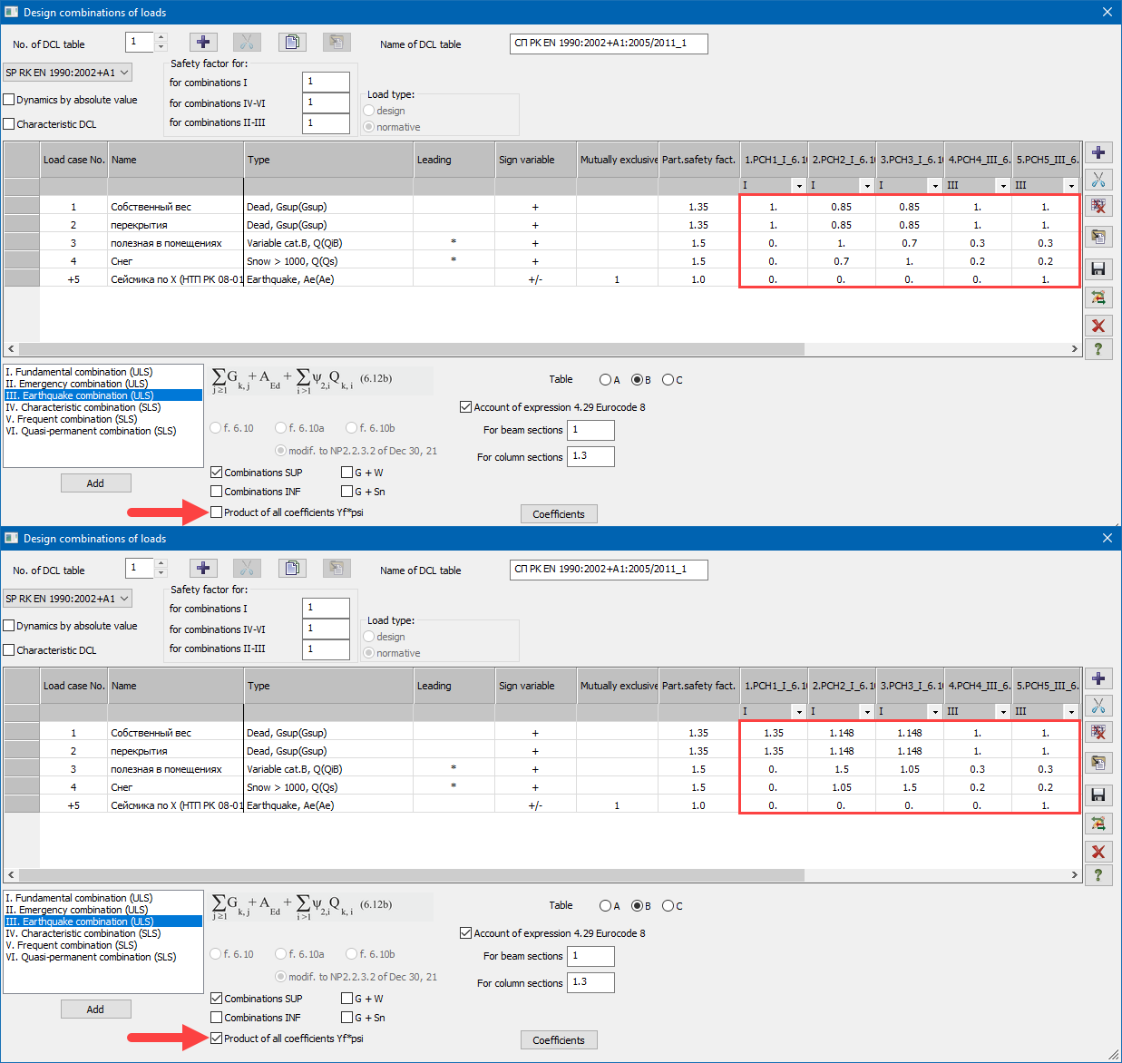
For SP RK EN 1990:2002+A1:2005/2011, the option to present the combination table 'explicitly', so the combination coefficients and reduction factors are corrected with account of the safety factors to the loads and the type of defined loads.
Important. In the current release, this option is implemented for the case when the normative loads are used in the model.
-
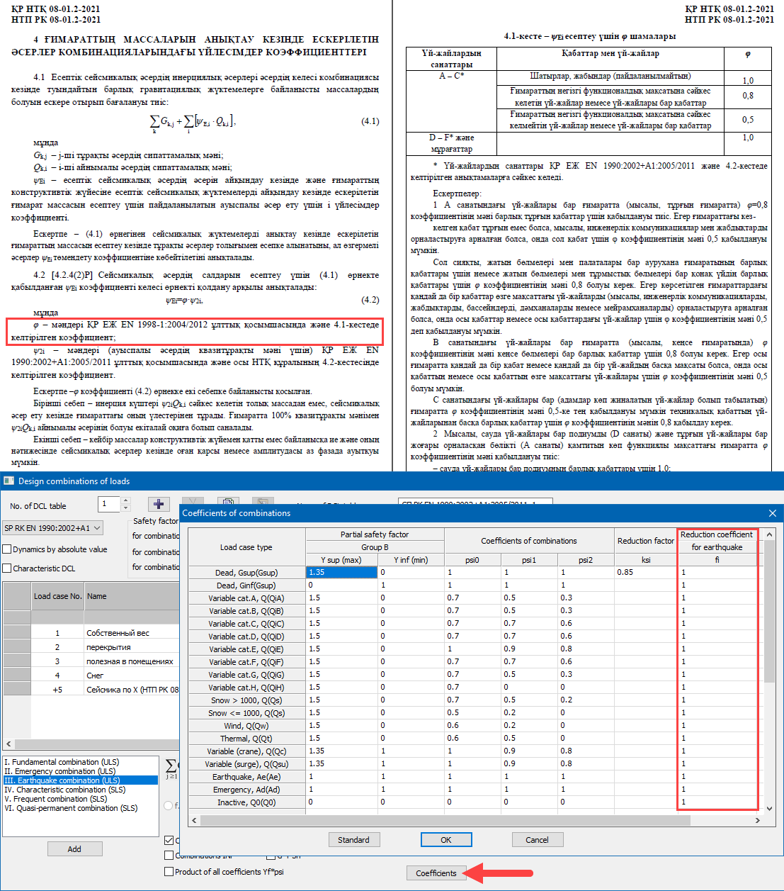
In the DCL table for the SP RK EN 1990:2002+A1:2005/2011, in the 'Coefficients' dialog box, new column with fi coefficients that reduce the contribution of the load case to the earthquake design combination. By default, all values are 1.
Note: According to the new NTP RK 08-01.2-2021 (see pages 43-45, chapter 4), it is necessary to reduce the contribution of some temporary loads to the generation of masses for earthquake load. Coefficients of combinations in the respective load types will be multiplied by the specified reduction coefficients fi. It is recommended to create a separate DCL table specifically to generate earthquake masses. The fi coefficients should be modified there and a DCL combination should be generated; the masses will be collected from this combination.
-
An input table for 'Coefficients to stiffness' related to subproblems.
-
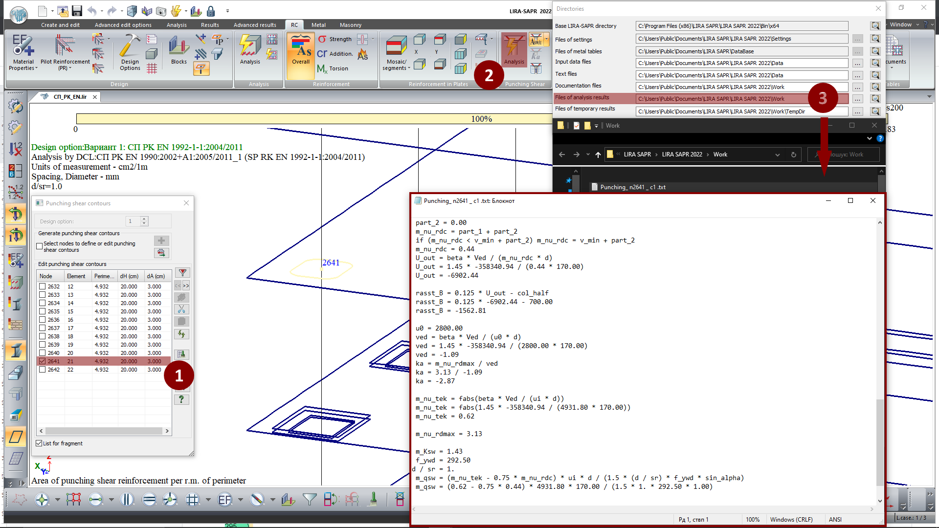
An option to control the generation of a tracing routine for the punching shear analysis of a certain contours by SP RK EN 1992-1-1:2004/2011 'Design of reinforced concrete structures'.
-
The high speed of DCL calculations is restored.
-
Enhanced generation of mosaic plots for the concentrated loads. Surface loads specified for plates and solids now are not considered in mosaic plots for the concentrated loads.
-
The data in the dialog boxes 'Edit load cases', 'Table of dynamic load cases' and 'Account of static load cases' is synchronized.
-
For 'collapsed' dynamic load cases, in the mode of analysis results' visualization, a table of coefficients may be pasted from the Clipboard. By default, the coefficients for the components will remain '1' in this case.
-
New commands on the ribbon user interface, new menus and toolbars in the classic user interface.
-
Numerous interface and other user requests are implemented.
FEM solver
-
Coefficient to stiffness (kE) may be applied to all nonlinear elements available in the analysis of post-stage load cases. So, the coefficients are applied to the linearised stiffnesses obtained in the analysis by 'NL Engineering 2'. This feature may be helpful, for example, when it is necessary (1) to use the diagrams for materials’ behaviour in long-term load, (2) to redistribute stiffnesses with account of cracks in RC sections and (3) for post-stage load cases (wind pulsation, impact/harmonic, earthquake), to transfer to the short-term modulus of elasticity.
-
For each dynamic load with specific criteria for termination of the iterative process (reaching the required number of total modal masses, ultimate frequency, etc.), after each iteration the program displays information about the accumulated total masses (for earthquake) and about the max calculated frequency (for pulsation components). According to this information the user could evaluate whether the iteration process should be continued or terminated to reduce the time for analysis.
-
In the analysis by the accelerograms with dynamics modules 27 and 29 for design models that consist of elements or fragments of structures with different damping properties, the analysis of equivalent damping for the j-th eigenvalue of vibrations is implemented according to the following formula: ξj={φj}T*∑[ξK]i*{φj}/{φj}T*[K]*{φj}
where {φj} is the vector of the j-th mode shape, [K] is the stiffness matrix for the model, ∑[ξK]i is the stiffness matrix for the i-th element or fragment of the structure multiplied by the damping ratio for that element.
SOIL
-
Calculation of elastic foundation ('Method 5') by formula (4) SNIP 2.02.05-87 'Foundations of machines with dynamic loads'. It enables the user to compute the coefficient of elastic uniform compression Cz (C1z) in dynamic loads on the foundation.
-
Stiffnes for one-node FE is calculated in order to simulate the shear stiffness of the soil base depending on the C1z assigned to the adjacent elements or on the C1z defined by the user.
Note: It is possible to calculate the stiffness of a one-node FE that simulates the rotational stiffness of the soil base around the vertical and horizontal axes. It should be noted that the linear stiffnesses distributed at the foundation base – subgrade moduli C1=Cz - also resist the rotation of the building. Therefore, the obtained rotational stiffnesses distributed across the foundation area on the one-node FEs at the appropriate nodes, should be modified by the user.
Tip: To introduce elastic springs in foundations, it is preferable to use FE57 rather than FE51, as in this case no extra stiffnesses will appear in the list of stiffness. In this case, to obtain mosaic plot of stiffness in FE57 for the visualization and the report, use the drop-down menu 'Mosaic plots of geometric properties of piles'.
-
New option to combine loads not only by %, but also by min absolute value. A global setting is added to the 'Options' menu.
-
Option to numerically display the properties of the geological element (GE) on the soil profile. This graphical representation may be used for documentation in the Report Book.
-
Direction of the local Z1-axes of horizontal plates is examined to exclude the positive soil pressure Rz. It is required so that the positive soil pressure Rz is not transferred to the input data in case C1/C2 is calculated iteratively.
-
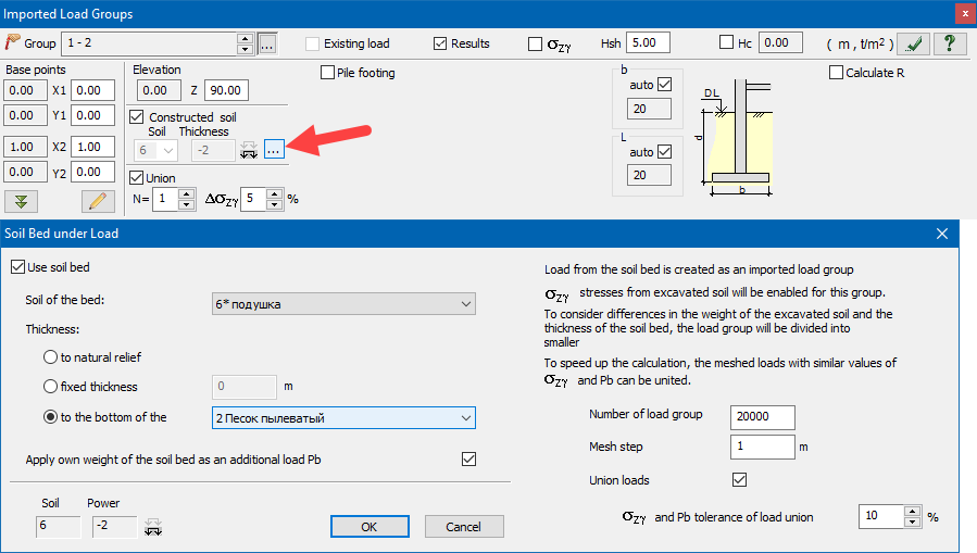
Expanded options to define the soil cushion:
- to generate a soil cushion of variable layer depth - 'Up to the bottom of the layer';
- to add the weight of the soil cushion to the additional loads (in this case, the natural pressure is considered only from the natural soil).
Notes:
In the first release of version 2022, there was new option to define parameters of the soil cushion for individual subgroups of imported loads. Now the whole set of new parameters may be also applied separately for different foundation fragments that the separate Pz subgroups are assigned to.
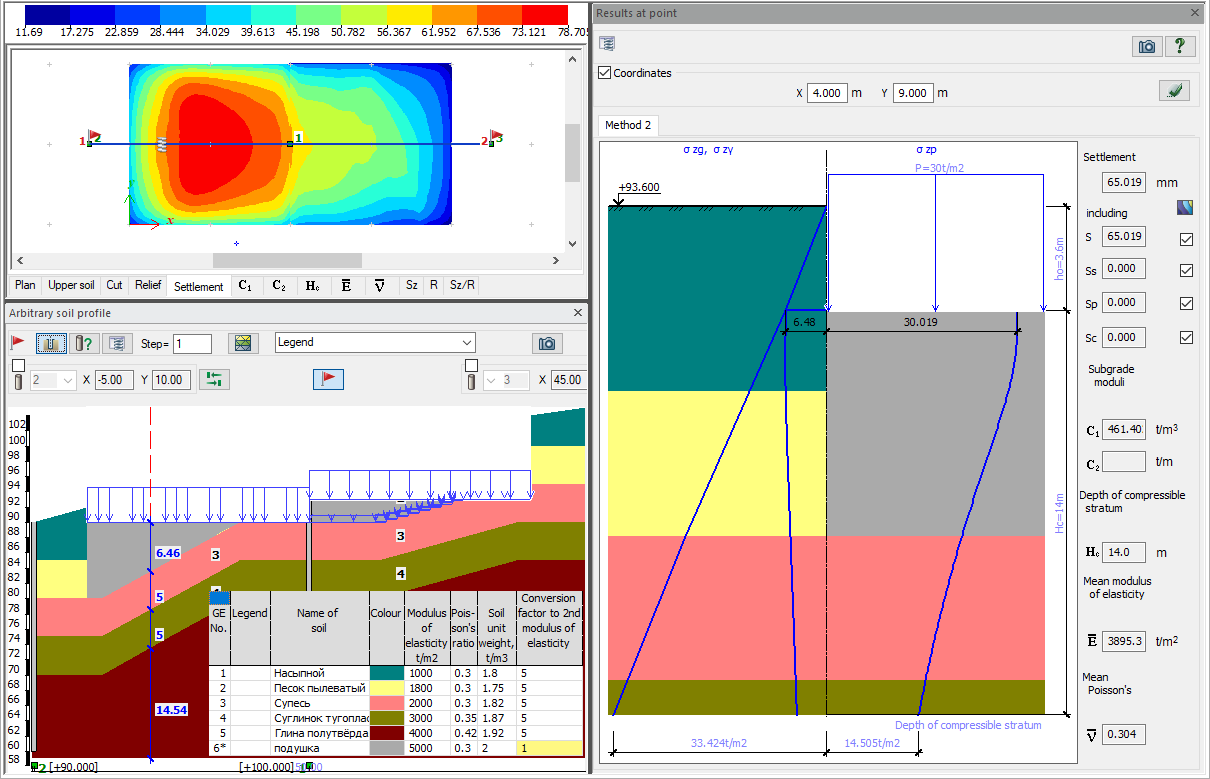
In LIRA-SAPR 2022 R1 and earlier versions, the soil cushion was considered as part of the natural soil. In this case, the diagram of natural pressure was generated from heavier soils (natural soils or soil cushion in order to calculate a more conservative result - a greater depth of compressible stratum). But the diagram from the weight of excavated soil (sigma-zy) is in all cases generated only from the natural soils. The important point is that for the soil cushion, the conversion factor to the 2nd modulus of elasticity should be defined as equal to 1, because the soil cushion is not deformed by the natural pressure of the natural soil.
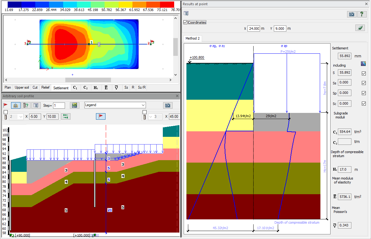
From LIRA-SAPR 2022 R2, it is possible to automatically generate the weight of the soil cushion and add it to the additional loads (including soil cushion of variable layer depth). So the soil cushion may be considered as part of the foundation and not the ground (so for this case the natural pressure is only considered from the natural soil).
The figure below considers a two-level foundation in which the natural soil is automatically replaced. In this case:
for the lower foundation, the soil cushion is defined as part of the natural soil (does not generate additional pressure - e.g. weak soil is replaced on the construction site, settlement from the weight of the soil cushion is complete, and then the foundation and basement structures are erected);
for the upper foundation, the soil cushion that replaces the weak soil is already a part of the foundation, as its weight affects the settlement of the available parts of the foundation and the plinth.
-
It is now possible to exclude the length of the offset from the pile length. Thus, the pile length from the bottom edge of the foundation slab to the pile toe can be specified in the input data.
ARM-SAPR (Reinforced Concrete Structures)
-
Option to check and select reinforcement based on the DCL(c) generated for problems with time history analysis.
-
For the SP RK EN 1992-1-1:2004/2011, the force combinations are divided into groups (fundamental, emergency and earthquake); the corresponding material properties are considered in the punching shear analysis.
-
For structural elements of columns where reinforcement is selected for flexibility by nominal curvature, a single output is available for the results of the selected areas for all elements in the structural element. This option is available for analysis according to SP RK EN 1992-1-1:2004/2011.
-
For SNIP 2.03.01-84*, in the material parameters 'Concrete', there is a new option 'Clarify the pattern of crack propagation'. When this option is active, analysis of longitudinal reinforcement for a plate element will be carried out regardless of the ratio of the core moment tensor and the crack propagation moment.
-
The calculation of the effective length factor for structural elements is corrected for SP RK EN 1992-1-1:2004/2011. In earlier versions, moments for calculating Meqv. were taken at the ends of the StE, but the effective length factor was taken from the lengths of the individual StE.
-
Output of results in case the 'Reinforcement was added according to strength in inclined sections'.
-
Modified algorithm for analysis of reinforcement in plate elements according to Karpenko's theory in buckling.
STC-SAPR (Steel Structures)
-
DBN B.2.6-198:2014 Amendment No. 1 is supported.
-
New check/selection of the section by the DCL(c) generated for problems with time history analysis.
-
In the local mode, for the element type 'column', a separate output of utilization ratio % is provided for tangential stresses. In previous versions, the results of this check were included in the final utilization ratio, so it was difficult to evaluate the analysis results.
SRS-SAPR (Steel Tables)
- New steel tables are added:
- DSTU 8539:2015 'Rolled steel for building steel structures';
- DSTU 8541:2015 'High-strength rolled steel products';
- DSTU 8938:2019 'Seamless hot-deformed steel pipes'.
BRICK (Masonry Structures)
-
In problems with time history analysis, it is possible to generate the graph for change in loads for brickwork levels.
Report Book (Documentation system)
-
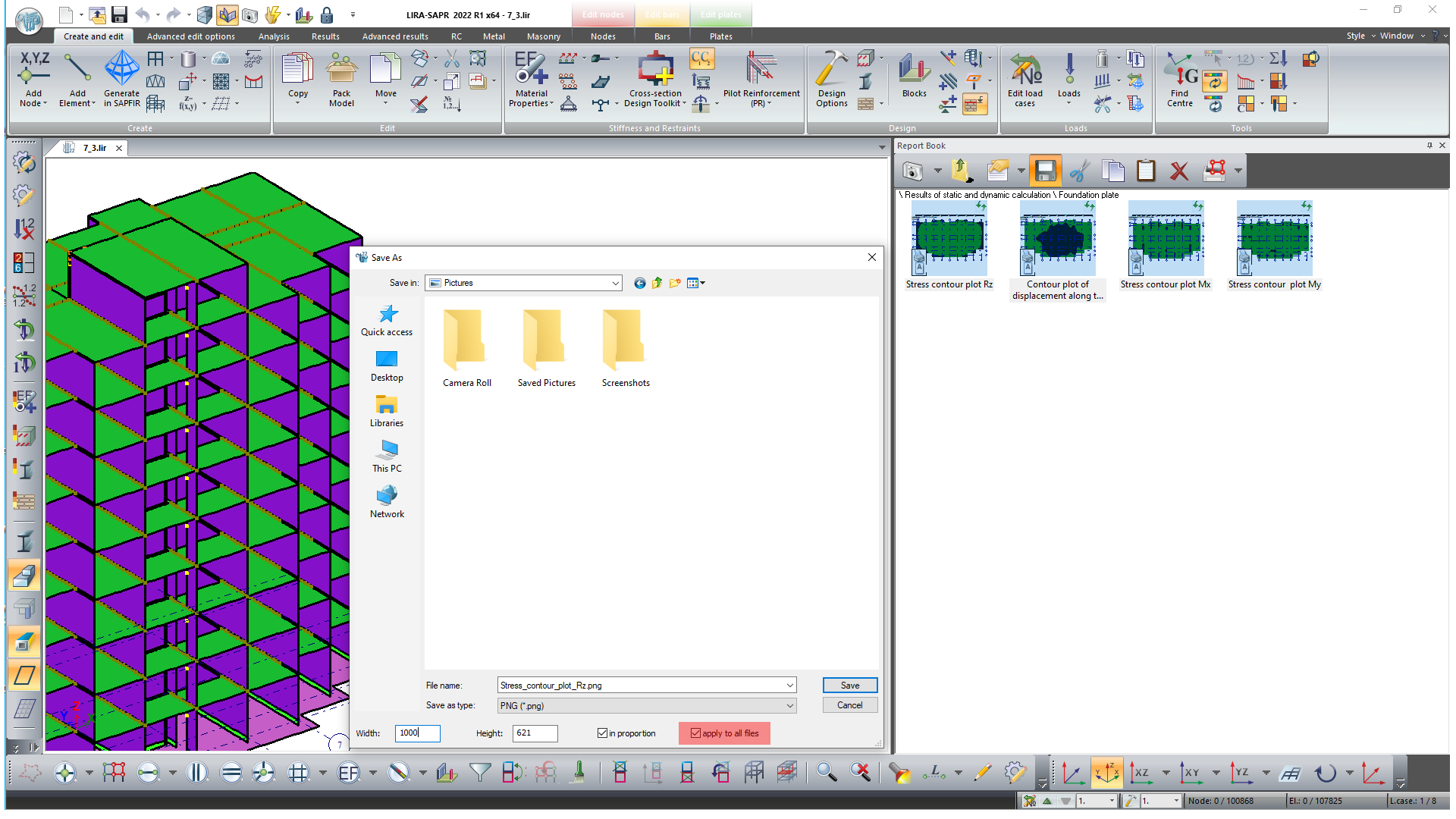
If a group of selected Report Book images is saved simultaneously and the 'Apply to all files' checkbox is selected, there is new option to resize the remaining images by enlarging or reducing the first image for which dimensions are shown in the corresponding boxes.
-
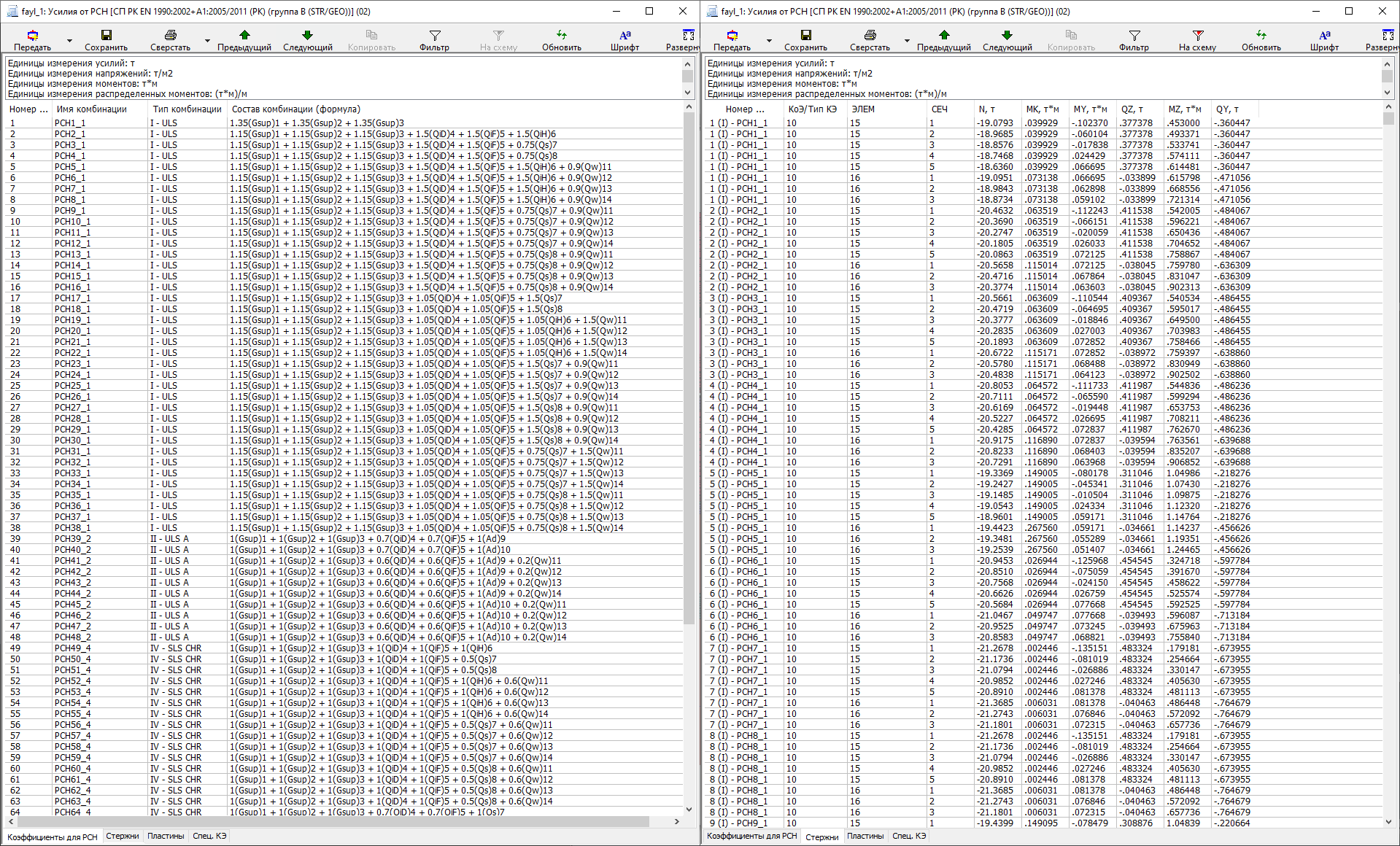
To control and document the input data, there is new option to present the DCL combinations with formula.
- New option to document soil and borehole properties and paginate this data.
- Option to save the graphs of changes in reactions over time in *.xls, *.csv format.
- A column with an index of a force group is added in the table of forces in the punching shear analysis.










Comments